


11
HARDWARE DESCRIPTION- Front Panel
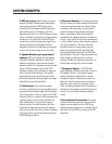
FRONT PANEL
The front panel of the DCM series resembles traditional cinema monitor products. This provides the projec-
tionist a well known and easy to understand interface.
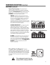
The Emergency Bypass switch setting alters the
Power Status of the Center Channel amplifier.
BYPASS switch set
to NORMAL
BYPASS switch set
to EMERGENCY
The Power Status of all amplifiers connected to the DCM
DataPorts will respond to the DCM power switch. When
the switch is in the ON position, all the amplifiers will be
on. When the switch is in the off position, all the amplifiers
will be in Standby mode.
Same as above EXCEPT that Center Channel (DataPort B
& C) will remain on even if the DCM Power switch is set
to the off position. For the DCM-1 only DataPort B
remains on.
The front panel TEST connections provide the same signal used to
drive the Monitor Speaker prior to the gain potentiometer (pre-fader).
TEST signal levels are the same level as the cinema processor output
signals (unity gain) and can be used for system calibration.
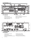
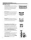
AMPS/PROC Selector Switch: The AMPS/PROC switch determines the function of the Monitor-
ing Select buttons, to the right of the AMPS/PROC switch. The LEDs directly over the PROC/AMPS
switch indicate what selected function the Monitor Select buttons will have. When the PROC LED is
illuminated, the Monitor Select buttons will select or deselect the various Cinema Processor inputs
to the DCM for monitoring. When the AMPS LED is illuminated, the Monitor Select buttons select
or deselect amplifier outputs for monitoring. After the AMPS/PROC choice has been made, the
individual channel buttons determine exactly which signals are routed to the front panel monitor
speaker.
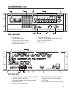
Monitor Output Speaker: The front panel speaker provides direct monitoring of the processor and
amplifier output audio signals. The Processor/Amps and Monitor source selection switches deter-
mine what is being monitored and the Monitoring Volume control determines the speaker’s output
level.
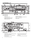
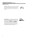
Power Switch: The power on/off switch is the master control for the DCM and
the amplifiers
connected to it. Amplifiers must be connected to the DCM with DataPort cables and power
switches must physically be in the “on” position. The DataPort connection to DCA amplifiers have a
standby control pin which provides standby control. QSC’s DCA amplifiers feature zero inrush
current, requiring no additional start-up sequencing. Center channel amplifier standby power
control can be bypassed using the BYPASS switch, see settings, below.