


17
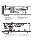
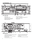
HARDWARE DESCRIPTION- Rear Panel
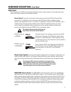
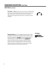
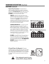
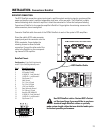
Terminal Strip Connections: The terminal strip in-
cludes convenient connections for output to a powered
subwoofer, a Hearing Impaired audio output, and on the
DCM-2 and 3, a remote control on/off logic connection
(EX MODE) for the surround decoder system.
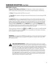
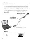
IEC-type AC Power Cord Receptacle: The power
receptacle accepts a standard IEC power cable. The DCM
uses a switching power supply that accepts a wide range
of AC voltage. 85 to 260 VAC (50/60 Hz.) is the acceptable
AC voltage. The IEC connector also houses the fuses for
the DCM.
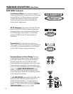
DCM-1 Terminal Strip Connections
DCM-2 and -3 Terminal Strip Connections
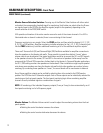
SUB OUT provides the exact same signal as the
subwoofer output used on DataPort G. It is assumed
that you use either DataPort G or the terminal strip
connection, but
not both
at the same time. This
connection cannot be monitored or include any of the
Fault Analysis functions because there are no connec-
tions
back
from this external speaker.
HEARING IMPAIRED OUT is a single mono audio
output which contains a mix of the L, C, and R
positional signals (Center = +6db compared to L&R).
This is usually connected to a special cinema system
which supplies headphones to people with hearing
difficulties. This can also be used as an input signal
to a powered speaker for remote monitoring of basic
L/C/R signals in larger projection booths.
EX MODE- On the DCM-2 and 3, this connection on
the terminal strip allows a remote on/off signal to
come from an external surround decoder. This routes
the surround signals (I/O) to the “TO SURROUND EX
DECODER” connector or directly to the DCM
DataPort connections.
If fuse replacement is required, use only
Littlefuse #218 001 or Bussman #S5504-1A.
REAR PANEL (continued)