


24
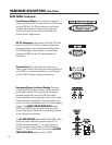
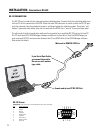
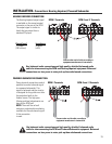
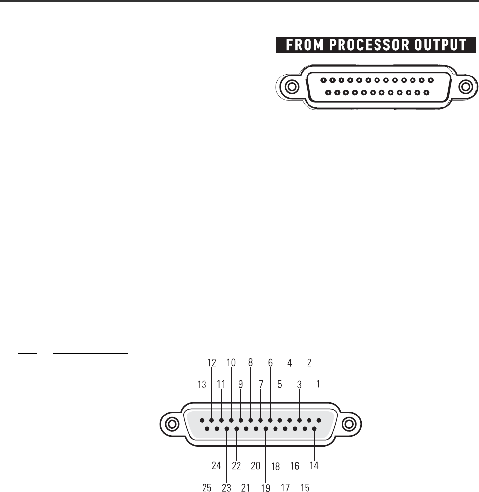
Audio signals are input to the DCM via the FROM
PROCESSOR OUTPUT connection. This DB25-type
connection conforms to cinema industry standard pinout.
Most common cinema processors use this DB25 connec-
tion standard, making connection to the DCM simple.
Orient the DB25-type connector properly, push gently to
seat the pins, then finger-tighten the retaining screws.
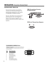
Cinema processors that do not use standard DB25-type connection typically have adapter cables available.
Check with the processor manufacturer. We recommended that you purchase a standard 25-pin cable from
any of the well known cinema industry cable suppliers.
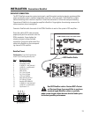
CINEMA PROCESSOR CONNECTION
INSTALLATION- Connections: Cinema Processor
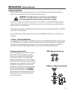
Configuration: 25-pin SubD male to 25-pin SubD
male.
Pin # Signal Description
1 Chassis Ground
2 Left +
3 Left Center -
4 Chassis Ground
5 Center +
6 Right Center -
7 Chassis Ground
8 Right +
9 Chassis Ground
10 Surround Left -
11 Surround Right -
12 Subwoofer -
13 Chassis Ground
14 Left -
15 Chassis Ground
16 Left Center +
17 Center -
18 Chassis Ground
19 Right Center +
20 Right -
21 (not used)
22 Chassis Ground
23 Surround Left +
24 Surround Right +
25 Subwoofer +
FROM PROCESSOR OUT Pinout-