


23
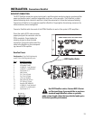
The QSC DataPort connection carries input signals, amplifier output monitoring signals, remote amplifier
power on/standby control, amplifier temperature, and more, all on one cable. Each DataPort is clearly
marked indicating which channel’s amplifier it should be connected to. Follow the back panel labeling.
Connect each DataPort to its respective amplifier’s DataPort. Finger-tighten the retaining screws on the
cable connectors; do not overtighten!
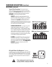
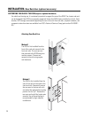
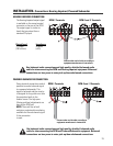
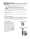
Connect a DataPort cable from each of the DCM’s DataPorts to each of the system’s DCA amplifiers.
Orient the cable’s HD15 male connector
properly and push the connector onto the
DCA’s receptacle. Finger-tighten the
retaining screws to ensure reliable
connection. Connect the other end of the
cable to the DataPort on the correspond-
ing channel’s DCA amplifier.
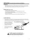
DATAPORT CONNECTION
Use QSC DataPort cables. Contact QSC’s Techni-
cal Services Group if you would like to purchase
standard length DataPort cables or specially
made custom length cables that use shielded audio-pairs
for the best possible performance.
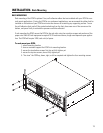
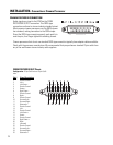
INSTALLATION- Connections: DataPort
DCM-1 DataPorts shown, other models similar.
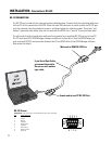
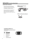
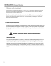
QSC DataPort Cable
Configuration: 15-pin SubD (high-density)
male to 15-pin SubD (high-density) male.
Pin # Signal Description
1 Ch. 1 Minus (-) Signal
2 AC Standby Control
3 V- MON Ch. 1 and Subcode 1
4 I- MON Ch. 1 and Subcode 2
5 Clip/Protect Ch. 1
6 Hard Ground
7 Ch. 1 Plus (+) Signal
8 Ch. 2 Plus (+) Signal
9 +15V from Amplifier
10 Data Reference Ground
11 Ch. 2 Minus (-) Signal
12 Amplifier IDR (Model ID)
13 V- MON Ch. 2 and Subcode 3
14 I- MON Ch. 2 and Subcode 4
15 Clip/Protect Ch. 2
DataPort Pinout-