


16
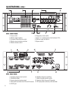
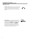
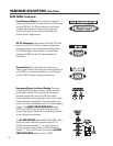
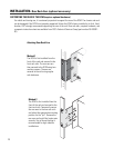
From Processor Output: This connection is from the
cinema processor, and is the input source of all film sound
into the DCM unit. The 25-pin connector is an industry
standard type and pinout, and will connect into your
system very easily. These cables are available from
several cinema supply houses.
HARDWARE DESCRIPTION- Rear Panel
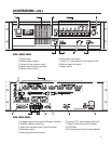
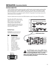
Emergency Bypass Levels and Routing: These are
used to adjust the passive crossover used by the Emer-
gency Bypass feature. The signal level of the passive
crossover outputs sent from the DCM to the center
channel amplifiers can be adjusted to best suit the center
channel transducer sensitivities. This signal path is only
active if the front panel Bypass switch is in the Emergency
position. The BYPASS CROSSOVER MODE switch
(DCM-2 and DCM-3 only) internally routes the Center
channel input signal through the 2-way passive crossover
or the 3 way passive crossover.
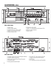
The BI-AMP ROUTING switch (DCM-2 and DCM-3 only)
routes the center channel low signal through CH1 of
DataPort B when in position “1”, or routes the center
channel low signal through CH2 of DataPort C when in
position “2”. The switch is not active when the BYPASS
CROSSOVER MODE switch is set to “3WAY”.
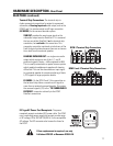
Surround Insert: The insert connector offers an ex-
tremely simple method of routing the surround signals out
of the DCM to an external processor box, and then back
into the DCM for further routing and monitoring.
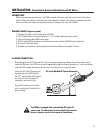
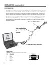
RS-232 Connection: This connects to the RS-232 serial
port on the host PC. All of the crossover functions and
many other features can be viewed and modified using
the DCM Manager control software. Communication
between the DCM and the PC is done through this
connection.
REAR PANEL (continued)