


15
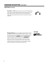
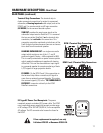
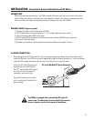
Amplifier DataPorts: One QSC amplifier DataPort includes all connections required to send two
channels of audio from the DCM to the amplifier input circuitry, and current and voltage information
back from the two speaker terminal outputs. Also included on this connector is remote on/standby
control of the amplifier which allows the DCM to act as a master system power controller.
Custom-length DataPort cables with individually shielded-pair construction are available from QSC’s
Technical Services Group.
The maximum output configuration on the DCM-1 is a 6 ch / 2-way, the maximum on the DCM-2 is a 6
ch / 3-way, and the maximum output configuration on the DCM-3 is a 8 ch / 3 way. In addition, many
parallel outputs (with separate processing) are included for additional theater configuration flexibility.
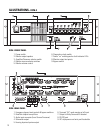
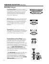
The rear panel labeling on the DCM has all of the information required by an audio installer. When
starting, write down the EXACT SPEAKER CONFIGURATION (for example, 8 channel, Tri-amp with 3
surrounds and 4 subs). Now you can follow the rear panel text which shows both channel position (L or
C or R, etc) and the frequency output (LO, MID, HI, etc). Connect the L-LO output to the correct amplifier
driving the left positional speaker’s low frequency transducer, and L-HI to the amplifier driving the same
speaker’s high frequency transducer, etc.
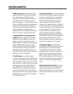
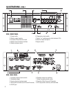
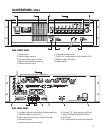
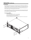
HARDWARE DESCRIPTION- Rear Panel
REAR PANEL
WARNING: Incorrect frequency connections can damage transducers. Physically
verify proper connections AND listen to each individual transducer at very low
volume before applying full audio power.
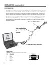
TYPICAL DCM DATAPORT LABELING (DCM-2 shown)-