


31
• Verify that the DCM Input Clip LED is not lit. If it is, the cinema processor output signal needs to be
turned down.
TROUBLESHOOTING
If theater audio is distorted ...
If switching the BYPASS to EMERGENCY does not restore sound to the center channel...
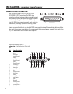
-DCM output level is adjusted using the DCM Manager software. Determine which channel’s
amplifier is clipping and make the necessary gain adjustments. This is done in the DSP Settings
tab. These gain settings compensate for driver sensitivity differences, so all the high and low (or
high, mid, low) gains should remain the same number of dB apart (compared to their factory
setting). There is no surround channel gain adjustment in the DCM.
-Amplifier input sensitivity adjustment: Refer to amplifier owner’s manual.
•If any of the amplifier CLIP warning LEDs are illuminating, the output level of the DCM must be reduced or
amplifier input sensitivity must be reduced.
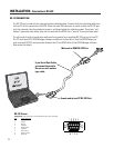
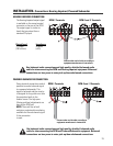
• Verify the DCM is receiving input signals from the Cinema Processor.
• Verify connections from the Cinema Processor to the DCM.
• Verify connections from the DCM to the center channel amplifier.
• Verify the Cinema Processor and center channel amplifier are ON and functioning.
• Verify the center channel amplifier’s Gain controls are set to a usable level.
• Verify center channel amplifier speaker connections and speaker condition.
NOTE: If the DCM unit is okay, place the Bypass switch back to the NORMAL position and the
Load Fault indicator will light (after a few minutes) if there was an open- or short-circuit in the
speaker cables.
NOTE: The Emergency Bypass circuitry in the DCM does not require power to operate. Even if the
DCM loses power, signals can be bypassed to the center channel as long as the remaining required
equipment is functioning properly.
If the DCM fails to turn on when the Power switch is set to the “on” position....
• Check the AC power cord and ensure both ends are fully inserted in their respective sockets.
• Check that the AC circuit being used is functioning. Test with a lamp or other known-good device.
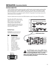
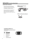
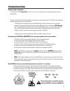
• Verify the condition of the fuses. They are located in the rear panel IEC power connector. Pry the
cover of the fuse holder, as shown, below. Inspect the fuses and replace if necessary.
If fuse replacement is required, use only
Littlefuse #218 001 or Bussman #S5504-1A.