


13
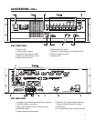
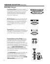
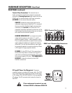
Diagnostics Check Button and Indicators: The Diagnostics / Indicator section includes an ex-
tremely simple method of verifying proper system operation and performing basic troubleshooting.
The Power LED shows whether the DCM unit is on or off.
The Input Clip LED is helpful in verifying that the cinema format processor is not over-driving the DCM
input circuitry.
The Load Fault indicator is a unique and powerful feature which verifies that signal inputs into the
DCM actually make it through the DCM, the DataPort cables, and the amplifier unit all the way to the
speakers, and that the speaker connections are not electrically shorted or open. All of these measure-
ments are being performed constantly (without user action) on ALL output channels and any unusual
readings will light the Load Fault LED. If the Load Fault LED is lit, pressing the Diagnostics button
(and holding it pressed) will cause the problem channel’s indicator LED to light. This information will let
you inspect the system cabling for that channel and troubleshoot the problem.
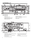
There are two types of indication: If the PROC LED and AMP LED are on, there is no amplifier detected
at that DCM amplifier connector. If the AMP LED is on, the amplifier on at that output is measuring a
short or an open on its output terminals.
REMEMBER: If you configured the DCM Manager software to not have certain channels (for example
there is no SUB 3 or SUB 4) or have not assigned a QSC amplifier to a channel, these channels WILL
NOT indicate any faults.
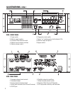
HARDWARE DESCRIPTION- Front Panel
FRONT PANEL (continued)
LOAD FAULT INDICATOR NOTE: The DCM’s Load Fault detection scheme uses a complex
averaging algorithm which compares input signals to output signals and measures voltage and
current on all amplifier outputs. To sense real world conditions, these measurements must be
found to be “out of range” many times before the Load Fault condition is indicated on the front
panel. If you are simulating fault conditions, you MUST have a “real-world” signal level
through the device (full signal input), and the fault condition must exist for several minutes
before the front panel Load Fault LED will light. This extra fault verification time eliminates
false triggering which would be confusing to a user. In conclusion,
Just shorting the output
terminals will NOT cause the fault LED to light,
the unit must be driven by real-world input
signals and the fault must persist for several minutes.