


Quality of Service 141
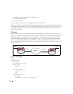
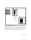
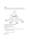
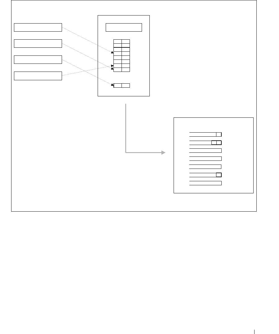
Figure 7-1. CoS Mapping and Queue Configuration
Continuing this example, you configured the egress Port 1/g8 for strict priority on queue 6, and a set a
weighted scheduling scheme for queues 5-0. Assuming queue 5 has a higher weighting than queue 1
(relative weight values shown as a percentage, with 0% indicating the bandwidth is not guaranteed), the
queue service order is 6 followed by 5 followed by 1. Assuming each queue unloads all packets shown in
the diagram, the packet transmission order as seen on the network leading out of Port 1/g8 is B, A, D, C.
Thus, packet B, with its higher user precedence than the others, is able to work its way through the
device with minimal delay and is transmitted ahead of the other packets at the egress port.
UserPri=3
packet A
UserPri=7
packet B
(untagged)
packet C
UserPri=6
packet D
Port 1/0/10
mode='trust dot1p'
0 2
1 0
2 1
3 5
4 4
5 5
6 5
7 6
802.1p->COS Q Map
port default
priority->traffic class
Port 1/0/8
AD
Q6
Q5
strict
weighted 20%
Q4 weighted 10%
Q3 weighted 5%
Q2 weighted 5%
C
Q1
Q0
weighted 0%
weighted 0%
Forward via
switch fabric to
egress Port 1/0/8
Ingress
Egress
Packet Transmission order: B, A, D, C
2 1
B
Port 1/g10
Port 1x/g8