


Routing Configuration 77
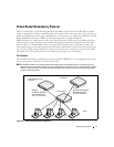
Virtual Router Redundancy Protocol
When an end station is statically configured with the address of the router that will handle its routed
traffic, a single point of failure is introduced into the network. If the router goes down, the end station is
unable to communicate. Since static configuration is a convenient way to assign router addresses, Virtual
Router Redundancy Protocol (VRRP) was developed to provide a backup mechanism.
VRRP eliminates the single point of failure associated with static default routes by enabling a
backup
router to take over from a
master
router without affecting the end stations using the route. The end
stations will use a
virtual
IP address that is recognized by the backup router if the master router fails.
Participating routers use an election protocol to determine which router is the master router at any given
time. A given VLAN routing interface may appear as more than one virtual router to the network. Also,
more than one VLAN routing interface
on a switch may participate in a virtual router.
CLI Examples
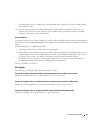
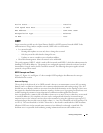
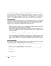
This example shows how to configure the switch to support VRRP. Router 1 is the default master router
for the virtual route, and Router 2 is the backup router.
NOTE:
The VRRP IP address on a routing interface must belong to the same subnet (primary or secondary) as the IP
address (primary or secondary) configured on that routing interface; otherwise, an error message displays and the
VRRP IP configuration fails. The master and backup VLAN routing interfaces must be in the same subnet and be
members of the same VLAN.
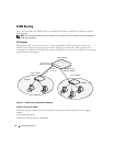
Figure 4-2. VRRP Example Network Configuration
` ` ``
VLAN 50
IP Address 192.150.2.1
Virtual Router ID 20
Virtual IP: 192.150.2.1
VLAN 50
IP Address 192.150.2.20
Virtual Router ID 20
Virtual IP: 192.150.2.1
Layer 3 Switch acting
as Router 1
Layer 3 Switch acting
as Router 2
Layer 2 Switch
Hosts