


Utility 171
Configuration Examples
The actual configuration of the feature is simple. NSF is either enabled or disabled. The examples in this
section describe how the NSF feature acts in various environments and with various switch applications.
Data Center
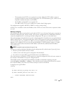
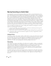
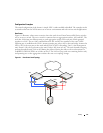
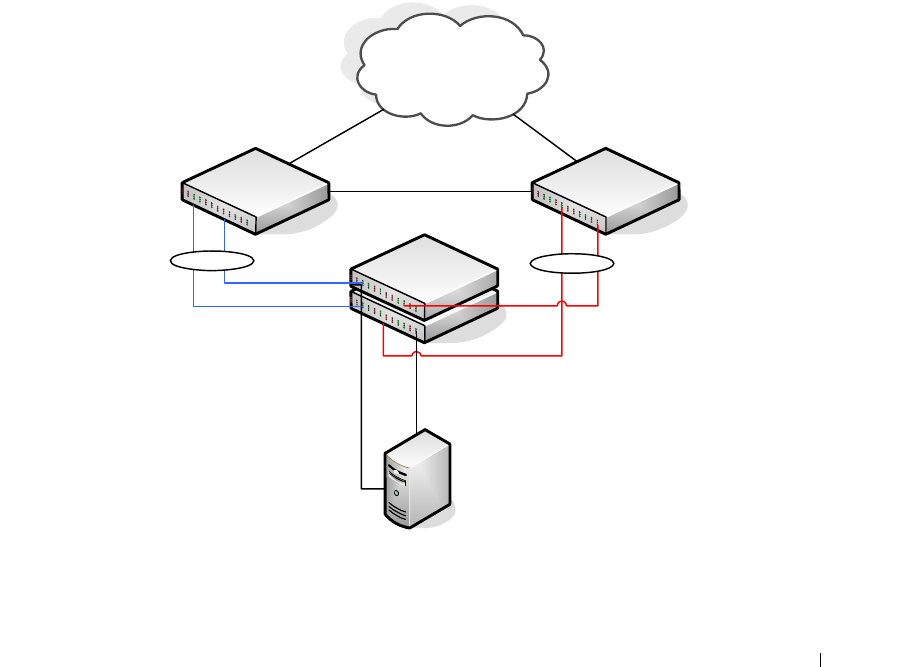
Figure 9-1 illustrates a data center scenario, where the stack of two PowerConnect 6200 Series switches
acts as an access switch. The access switch is connected to two aggregation switches, AS1 and AS2. The
stack has a link from two different units to each aggregation switch, with each pair of links grouped
together in a LAG. The two LAGs and link between AS1 and AS2 are members of the same VLAN.
Spanning tree is enabled on the VLAN. Assume spanning tree selects AS1 as the root bridge. Assume the
LAG to AS1 is the root port on the stack and the LAG to AS2 is discarding. Unit 1 is the management
unit. If unit 1 fails, the stack removes the unit 1 link to AS1 from its LAG. The stack forwards outgoing
packets through the unit 2 link to AS1 during the failover. During the failover, the stack continues to
send BPDUs and LAG PDUs on its links on unit 2. The LAGs stay up (with one remaining link in each),
and spanning tree on the aggregation switches does not see a topology change.
Figure 9-1. Data Center Stack Topology
LAG1
LAG2
Unit 1
Unit 2
AS1
AS2