


42 Switching Configuration
9.
View information about the IGMP snooping configuration.
console#show ip igmp snooping
Admin Mode..................................... Enable
Multicast Control Frame Count.................. 0
Interfaces Enabled for IGMP Snooping........... None
Vlans enabled for IGMP snooping................ 100
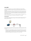
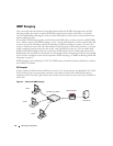
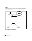
In this example, Host A sends a join message for group 225.1.1.1. Host B sends a join message for group
225.1.1.2. Because IGMP snooping is enabled on the switch and on VLAN 100, the switch listens to the
messages and dynamically adds ports 1/g5 and 1/g10 to the multicast address table. Port 1/g15 did not
send a join message, so it does not appear in the table, as the following show command indicates.
console#show bridge multicast address-table
Vlan MAC Address Type Ports
---- ----------------------- ------- -----------------
100 0100.5E01.0101 Dynamic 1/g5
100 0100.5E01.0102 Dynamic 1/g10
Forbidden ports for multicast addresses:
Vlan MAC Address Ports
---- ----------------------- ----------------------
100 0100.5E01.0101
100 0100.5E01.0102
When the video server sends multicast data to group 225.1.1.1, port 1/g5 participates and receives
multicast traffic, but port 1/g10 does not participate because it is a member of a different multicast
group. Without IGMP snooping, all ports that are members of VLAN 100 would be flooded with traffic
for all multicast groups, which would greatly increase the amount of traffic on the switch.
You can use the show statistics command to view information about the multicast data transmitted or
received by each interface. The following output shows a portion of the command output for interfaces
1/g5 and 1/g10. In this example, the counters were cleared before the video server began transmitting
data.
console#show statistics ethernet 1/g5
...
Total Packets Received Without Errors.......... 626494
Unicast Packets Received....................... 0