


Routing Configuration 89
Example 3: Configuring a Virtual Link
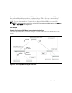
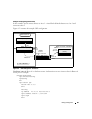
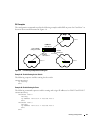
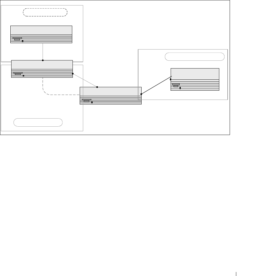
In this example, Area 0 connects directly to Area 1. A virtual link is defined that traverses Area 1 and
connects to Area 2.
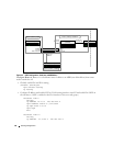
Figure 4-5 illustrates this example OSPF configuration.
Figure 4-5. OSPF Configuration—Virtual Link
Configure Router A: Router A is a backbone router. Configuration steps are similar to those for Router A
in the previous example.
(console)#configure
ipv6 unicast-routing
ip routing
exit
ipv6 router ospf
router-id 3.3.3.3
exit
interface vlan 5
routing
ip address 10.2.3.3 255.255.255.0
ipv6 address 3000:2:3::/64 eui64
ipv6 ospf
exit
Router B - ABR (4.4.4.4)
Virtual Link
10.1.101.1
3000:1:101::/64
10.1.2.2/24
3000:1:2::/64 eui64
10.2.3.2
3000:2:3::/64
Area 2 (0.0.0.2)
IR (5.3.0.0)
Area 1 (0.0.0.1)
Router C - ABR (5.5.5.5)
10.1.2.1/24
3000:1:2::/64
10.2.3.3/24
3000:2:3::/64
Router A - backbone
(3.3.3.3)
Area 0 (0.0.0.0) - backbone
VLAN 10
VLAN 7
VLAN 11
VLAN 2
VLAN 5