


B-4 Dell PowerEdge 6300 Systems User’s Guide
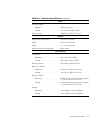
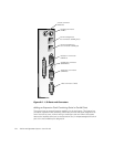
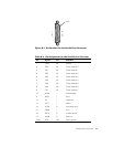
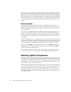
)LJXUH%3LQ1XPEHUVIRUWKH6HULDO3RUW&RQQHFWRUV
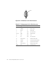
3D UD OOHO3RUW&RQQHFWRU
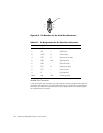
If you reconfigure your hardware, you may need pin number and signal information for
the parallel port connector. Figure B-3 illustrates the pin numbers for the parallel port
connector, and Table B-2 lists and defines the pin assignments and interface signals
for the parallel port connector.
7DEOH%3LQ$VVLJQPHQWVIRUWKH6HULDO3RUW&RQQHFWRUV
3LQ 6LJQDO ,2 'HILQLWLRQ
1 DCD I Data carrier detect
2 SIN I Serial input
3 SOUT O Serial output
4 DTR O Data terminal ready
5 GND N/A Signal ground
6 DSR I Data set ready
7 RTS O Request to send
8 CTS I Clear to send
9 RI I Ring indicator
Shell N/A N/A Chassis ground
1 — 5
6 — 9
shell