


I/O Ports and Connectors B-7
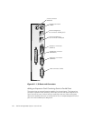
0RXV H &R QQ HF WR U
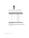
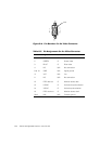
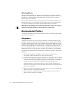
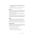
If you reconfigure your hardware, you may need pin number and signal information for
the mouse connector. Figure B-5 illustrates the pin numbers for the mouse connector,
and Table B-4 lists and defines the pin assignments and interface signals for the
mouse connector.
)LJXUH%3LQ1XPEHUVIRUWKH0RXVH&RQQHFWRU
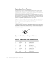
9LGHR&RQQHFWRU
The system uses a 15-pin high-density D-subminiature connector on the back panel
for attaching a video graphics array (VGA)-compatible monitor to your system. The
video circuitry on the system board synchronizes the signals that drive the red, green,
and blue electron guns in the monitor.
NOTE: Installing a video card automatically disables the system’s built-in video
subsystem.
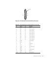
If you reconfigure your hardware, you may need pin number and signal information for
the video connector. Figure B-6 illustrates the pin numbers for the video connector,
and Table B-5 lists and defines the pin assignments and interface signals for the video
connector.
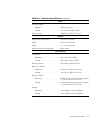
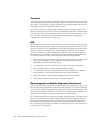
7DEOH%3LQ$VVLJQPHQWVIRUWKH0RXVH&RQQHFWRU
3LQ 6LJQD O ,2 'HILQL W L R Q
1 MFDATA I/O Mouse data
2 NC N/A No connection
3 GND N/A Signal ground
4 FVcc N/A Fused supply voltage
5 MFCLK I/O Mouse clock
6 NC N/A No connection
Shell N/A N/A Chassis ground
2
4
6
5
3
1
shell