


Installing System Components 47
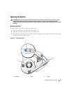
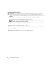
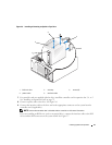
Closing the System
Replacing the Cover
1
Ensure that all cables are connected, and fold cables out of the way.
2
Ensure that no tools or loose parts are left inside the system.
3
Fit the cover on the side of the system, and slide the cover backward.
4
Tighten the cover thumbscrew to secure the cover.
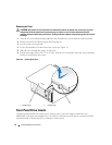
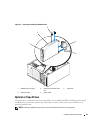
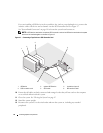
Installing the Bezel
To install the bezel, align the hooks at the bottom of the bezel, swing the top of the bezel toward the system,
and press the bezel onto the system until it snaps into place. Using the system key, lock the bezel.
Connecting Drives
Interface Cables
Most interface connectors are keyed for correct insertion. Keying ensures that the pin-1 wire in the cable
connects to pin 1 in the connectors on both ends. When you disconnect an interface cable, take care to
grasp the cable connector, rather than the cable itself, to avoid stress on the cable.
Drive Cable Configurations
Your system can accommodate many different drive configurations, each with specific cable requirements.
Table 3-1 shows the cable requirements for common drive configurations.
Table 3-1. Drive Cable Configuration
Drives Required Cable Cable Connections
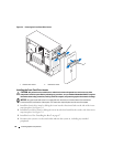
IDE optical drives, internal IDE and
external SCSI tape drives (with
optional SCSI HBA card) (See
Figure 3-7.)
80-pin IDE 2-drop cable or
external SCSI cable
IDE drive and primary IDE
connector on system board or
external SCSI tape device (with
option SCSI HBA card)
Up to four cabled SATA hard drives
(non-hot-plug) (See Figure 3-9.)
7-pin SATA hard-drive cable
(one cable per drive)
SATA hard drives and SATA port
connectors on the system board,
or via SAS controller card
Up to four cabled (non-hot-plug)
SAS hard-drives (See Figure 3-13.)
32-pin 1- to 4-drop SAS cable SAS hard drives connected to
SAS controller card
Up to four SAS or SATA hard drives
connected to the SAS backplane (hot
plug) (See Figure 3-12.)
32-pin SAS backplane cable SAS backplane connected to the
SAS controller card