


Installing System Components 87
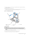
Installing the Control Panel Assembly
1
Insert the control panel assembly cable and chassis-intrusion switch through the front of the system.
2
Thread the chassis-intrusion switch upward through the opening above the control panel slot.
3
Connect the control panel assembly cable connector to the FRONT_PANEL connector on the system
board and insert the cable in its guide bracket.
4
Guide the chassis-intrusion switch cable through the three holding clips underneath the front lip of
the system chassis.
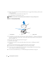
5
Insert the chassis-intrusion switch into its slot in the front of the chassis, then slide the switch down
into place.
6
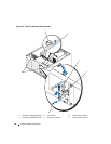
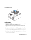
Using a #2 Phillips screwdriver, install the screws that secure the control panel assembly to the chassis.
See Figure 3-25.
7
Close the system. See "Closing the System" on page 47.
8
Stand the system upright.
9
Reconnect the system to its electrical outlet and turn the system on, including any attached
peripherals.
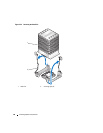
System Board (Service-Only Parts Procedure)
The system board and system board tray are removed and replaced as a single assembly.
CAUTION: Only trained service technicians are authorized to remove the system cover and access any of the
components inside the system. Before performing any procedure, see your Product Information Guide for
complete information about safety precautions, working inside the computer, and protecting against electrostatic
discharge.
CAUTION: The processor heat sink can get hot during operation. To avoid burns, ensure that the system has
sufficient time to cool before removing the system board.
Removing the System Board
1
Turn off the system and attached peripherals, and disconnect the system from the electrical outlet.
2
Disconnect the cables to the I/O connectors on the back panel.
3
Open the system. See "Opening the System" on page 43.
4
Disconnect the two power cables from connectors PWR_CONN and 12V on the system board.
5
Remove the cooling shroud. See "Removing the Cooling Shroud" on page 64.
6
If the system has cabled SAS drives or SATA drives, note the relative location of the interface cable
connections between the system board and the drives, so you can reconnect them in the proper
sequence.
7
Disconnect the SAS or SATA interface cable(s) connected to the system board or optional hard-drive
controller card.