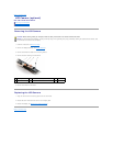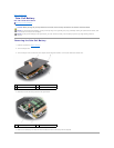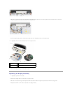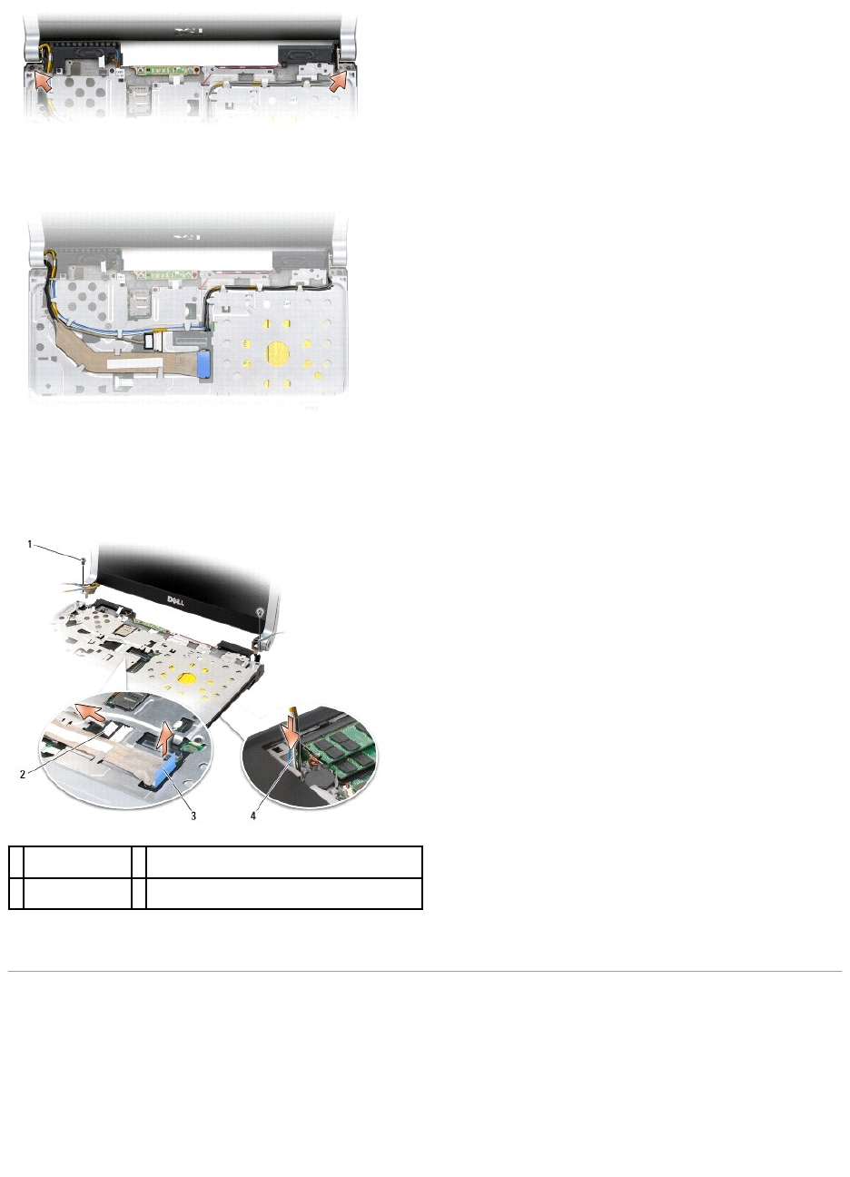
8. Make note of the cable routing and carefully dislodge the Mini-Card antenna cables from their routing guides and pull the cables with their connectors
through the system board so that they are clear of the computer base.
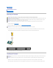
9. Pull on the display cable pull-tab to disconnect the display cable from the display connector on the system board.
10. If applicable, remove the camera cable connector from the system board.
11. Remove the display assembly from the computer base.
Replacing the Display Assembly
1. If applicable, replace the camera cable.
2. Reconnect the display cable to the connector on the system board.
3. Make note of the cable routing and carefully slide the Mini-Card antenna cables through the computer base and into their routing guides.
4. Replace the two M2.5 x 5-mm screws on each side of the display assembly.
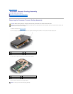
1
M2.5 x 5-mm
screws (2)
2
camera cable connector (optional)
3
display cable pull-
tab
4
Mini-Card antennae cables (view from the bottom
of the computer)


