Configuring L2 Multicast Features 855
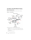
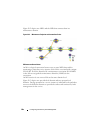
• Multicast Sources: Server A – 239.20.30.40, Server B – 239.20.30.42
• Subnets: VLAN 10 – 192.168.10.x, VLAN 20 – 192.168.20.x
• Mrouter ports: D3 – 1/0/20, D2 – PortChannel1, D1 – 1/0/15
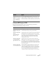
Snooping Within a Subnet
In the example network topology, the multicast source and listeners are in the
same subnet VLAN 20
–
192.168.20.x/24. D4 sends periodic queries on VLAN
10 and 20, and these queries are forwarded to D1, D2, and D3 via trunk links.
Snooping switches D1, D2, and D3 flood these queries in VLANs 10 and 20
to clients G, F, and D, respectively.
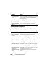
Multicast Source and Listener directly connected to a snooping switch:
Server B Client G
1
Client G sends a report for 239.20.30.42.
2
The report is forwarded to multicast router D4 via D1 – 1/0/15 and D3 –
1/0/20.
3
A forwarding entry is created by D1 for VLAN 20, 239.20.30.42 – 1/0/8,
1/0/15.
4
Client G receives the multicast stream from Server B.
5
D3 receives the multicast stream and it is forwarded to D4 because D4 is a
multicast router.
6
Client D sends a report for 239.20.30.42.
7
The report is forwarded to multicast router D4 via D3 – 1/0/20.
8
A forwarding entry is created by D3 for VLAN 20, 239.20.30.42 – 1/0/6,
1/0/20.
9
Client D receives the multicast stream from Server B.
10
Client F does not receive the multicast stream because it did not respond
to queries from D4.
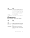
Multicast Source and Listener connected by intermediate snooping switches:
Server B Client D
1
Client D sends a report for 239.20.30.42.
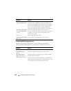
2
The report is forwarded to multicast router D4 via D3 – 1/0/20.


