


950 Configuring Link Aggregation
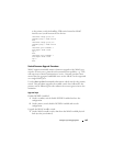
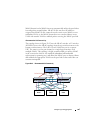
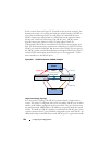
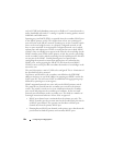
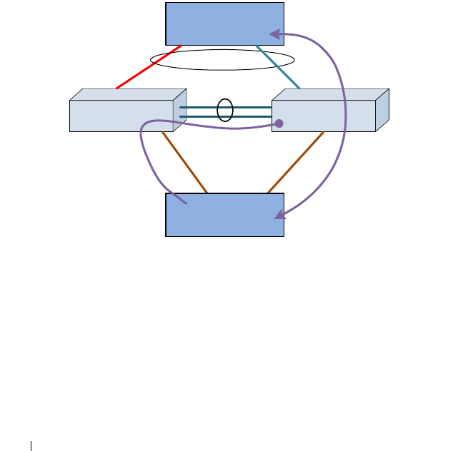
In the scenario shown in Figure 28-15(similar to the previous scenario), the
downstream router is not configured with port-channel and uses ECMP or
some other load sharing scheme to send packets to routed MLAG peers.
MLAG cannot react appropriately to a link failure on the upstream router
because the VLANs are routed across the MLAG peers. MLAG cannot
logically connect the failure on VLAN 30 with orphan VLAN 20.
Consequently, MLAG does not unblock VLAN 20 from traversing the peer
link. The downstream router continues to send packets on VLAN 20 to the
MLAG peer with the failed link. But because routed VLAN 20 is not part of
the MLAG, packets remain blocked when transiting the MLAG peer link. L3
routed VLANs termination on the MLAG peers is not supported—VLANs
must extend across the MLAG peers.
Figure 28-15. L3 VLAN Termination on MLAG, Example 2
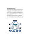
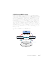
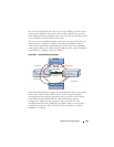
Degenerate Routing Topology
In a “one-armed” topology, the MLAG is partnered with a single router or
switch. The router is configured with a LAG toward the MLAG peer switches
and has an IP address configured on the router LAG. The peer switches may
be configured with VRRP and have IP addresses assigned to both the routed
VLANs. If a multi-tier MLAG topology is used below the MLAG peers, these
switches must not have L3 port-channels configured as part of the MLAG. An
additional backup routed link between the MLAG peers is required to handle
MLAG Router PeerMLAG Router Peer
Peer-Link
Router
MLAG
VLAN 30
Failed Link
VLAN 20
Router