Dell™ PowerEdge™ R610 Technical Guidebook
11
I. Fans
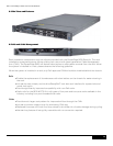
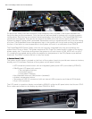
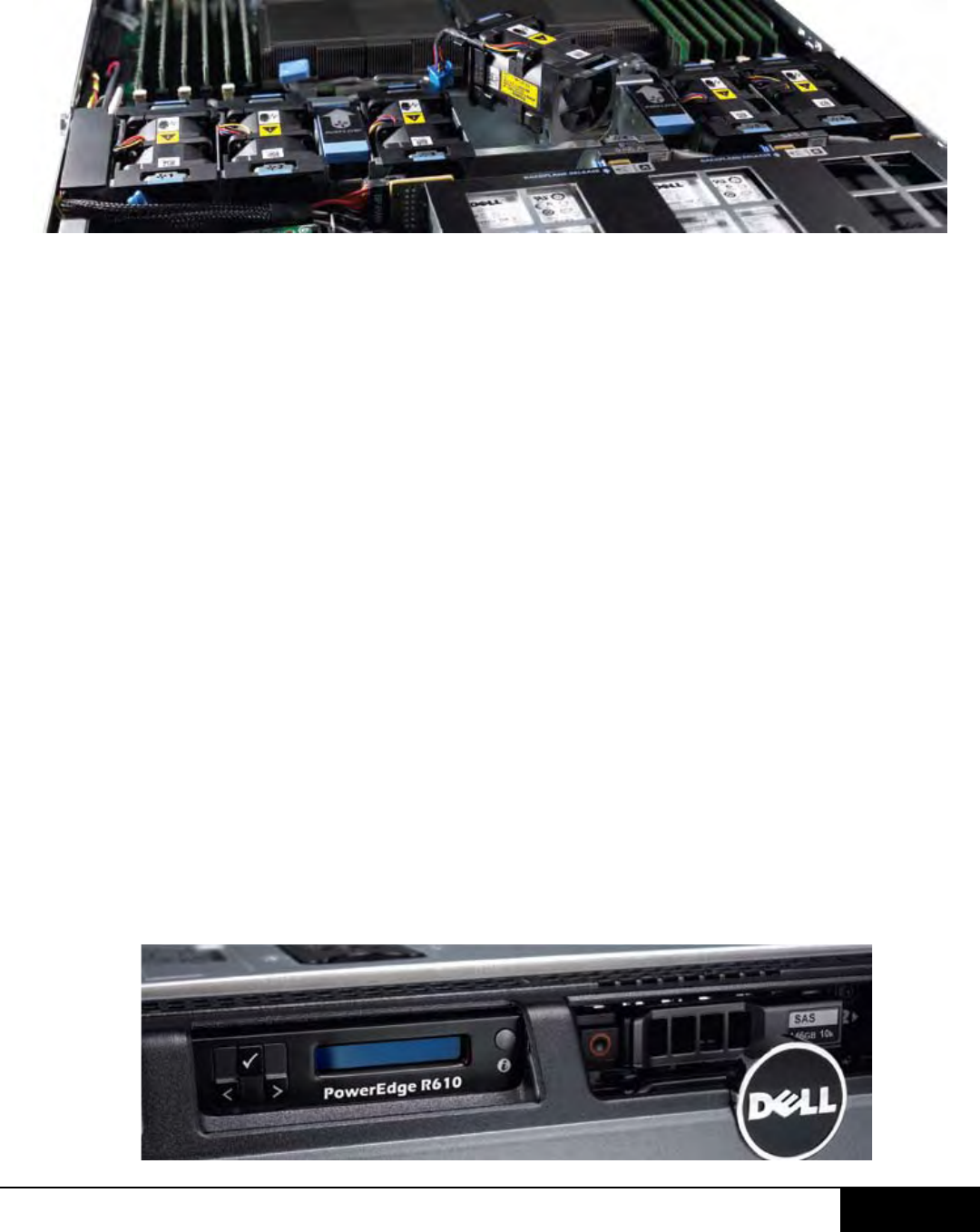
Six dual-rotor 40mm fans are mounted in a fan assembly that is located in the chassis between the
hard drive bay and the processors. Only five fans will be populated in systems with a single processor
configuration. Each fan has a connector that plugs directly into the planar. (The PowerEdge R610 fans
cannot be hot-swapped. There are six fan zones in the R610, with one zone for each system fan.)
System fan speed is pulse-width modulated. Redundant cooling is supported with only one rotor failing
at a time. The Embedded Server Management logic in the system will control and monitor the speed of
the fans. A fan failure or over-temperature in the system will result in a notification from iDRAC6.
The PowerEdge R610 Power Supply Units do not have any integrated fans; they are cooled by the
system fans in front of them. The system requires a PSU Close Out (metal cover) in place of the empty
power supply slot. To provide cooling when the system is o, both rotors in FAN_MOD1 will run o of
V
aux
power at a low speed setting when the ambient air temperature in the PSU passes a pre-defined
threshold. The iDRAC controls the fan in AutoCool mode.
J. Control Panel / LCD
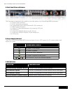
The system control panel is located on the front of the system chassis to provide user access to buttons,
display, and I/O interfaces. Features of the system control panel include:
•ACPI-compliantpowerbuttonwithanintegratedgreenpowerLED(controlledbyiDRAC6)
•128x20pixelLCDpanelwithcontrols
•Twonavigationbuttons
•Oneselectbutton
•OnesystemIDbutton
•Non-MaskableInterrupt(NMI)button(recessed)
•Ambienttemperaturesensor
•TwoexternalUSB2.0connectors(withaninternalUSBconnectorandInternalSDModule)
•15-pinVGAconnector
The LCD panel is a graphics display controlled by iDRAC6, unlike the 9G panel which had its own CPLD.
Error codes can be sent to the display by either iDRAC6 or BIOS.


