Dell™ PowerEdge™ R610 Technical Guidebook
9
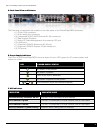
D. Back Panel View and Features
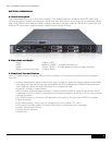
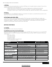
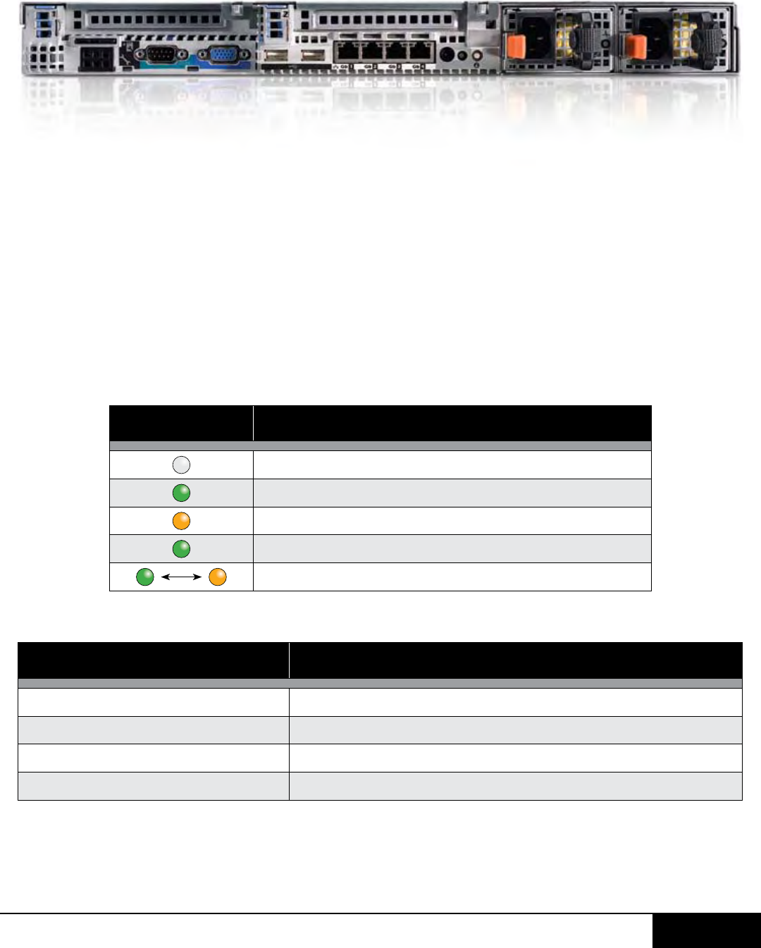
The following components are located on the rear panel of the PowerEdge R610 enclosure:
•(1)15-pinVGAconnector
•(1)9-pinserialportconnector
•(4)Integrated10/100/1000EthernetRJ-45connectors
•(1)RearsystemIDbutton
•(1)ActiveIDCableManagementArmexternalLEDjack
•(2)USBports
•(1)(Optional)iDRAC6EnterpriseRJ-45port
•(1)(Optional)iDRAC6ExpressVFlashmediaslot
•(2)PCIeslots
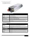
E. Power Supply Indicators
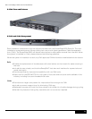
The PSUs on the PowerEdge R610 have one status bi-color LED: green for AC power present and
amber for a fault.
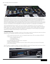
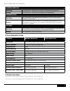
F. NIC Indicators
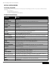
LED POWER SUPPLY STATUS
AC power is not present
AC power is present
Fault of any kind is detected
DC power is applied to the system
PSU mismatch (when hot-added/swapped)
INDICATOR INDICATOR CODE
Link and activity indicators are off
The NIC is not connected to the network
Link indicator is green
The NIC is connected to a valid network link at 1000 Mbps
Link indicator is amber
The NIC is connected to a valid network link at 1000 Mbps
Activity indicator is green blinking
Network data is being sent or received


