Dell™ PowerEdge™ R610 Technical Guidebook
37
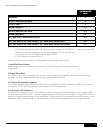
POWEREDGE
R610
Platforms
4
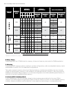
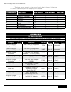
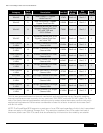
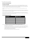
All 2.5" HDD SAS (or) SATA
4
All 2.5" SSD***
4
Mixed SSD/SAS**
N/A
All 3.5" HDD SAT (or) SATA
N/A
Mixed SAS/SATA*
4
2.5" SAS in 3.5" HDD Carrier (RTS+)
N/A
2.5" SAS HDD in 3.5" HDD Carrier + 3.5" SATA HDDs (Mixed SAS)
N/A
2.5" SAS HDD in 3.5" HDD Carrier + 3.5" SATA HDDs (Mixed SAS/SATA)*
N/A
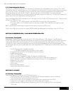
•SASHDDsshouldbeinslots0&1andmin/maxnumberofSASHDDsis2,therestwillbeSATA
HDDs and min/max number of SATA HDDs depends on the configuration.
•**NomaximumforSASHDD’scombinedwithSSD
•***SSDSupportrequiresPERC6/i
20GBand50GBsolidstatedrives(SSD)supportwillbesupportedatRTS
I. Hard Disk Drive Carriers
HarddrivesmustusetheDelldrivecarrierfor2.5"drives(legacydrivecarriersarenot
supported).
II. Empty Drive Bays
For the slots that are not occupied by drives, a carrier blank is provided to maintain proper cooling,
maintain a uniform appearance to the unit, and provide EMI shielding.
III. Diskless Configuration Support
The system supports diskless configuration with no storage controller (SAS 6/iR or PERC 6i) installed in
thesystem.A2.5"HDDbackplaneisstillinstalledinthisconguration.
IV. Hard Drive LED Indicators
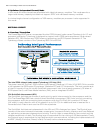
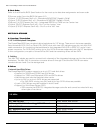
Each disk drive carrier has two LED indicators visible from the front of the system. One is a green LED
for disk activity and the other is a bicolor (green/amber) LED for status information. The activity LED is
driven by the disk drive during normal operation. The bicolor LED is controlled by the SEP device on the
backplane. Both LEDs are used to indicate certain conditions under direction of a storage controller.


