


Installing System Components 101
4
Remove all expansion cards and any attached cables. See "Removing an
Expansion Card" on page 70.
5
Remove all memory modules. See "Memory" on page 75.
NOTE: Record the memory-module socket locations to ensure proper
reinstallation of the memory modules.
CAUTION: The processor and heat sink can become extremely hot. Allow
sufficient time for the processor and heat sink to cool before handling.
NOTICE: To prevent damaging the processor, do not pry the heat sink off of the
processor.
6
Remove the processor. See "Removing the Processor" on page 79.
7
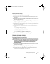
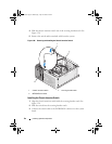
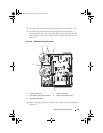
Using a #2 Phillips screwdriver, remove the six system board mounting
screws that secure the system board to the chassis. See Figure 6-2.
8
Using a #2 Phillips screwdriver, remove the two processor heat sink pivot
mount screws and remove the pivot mount from the system board. See
Figure 6-2. The heat sink pivot mount screws are green and are longer than
the system board mounting screws.
9
Carefully route any loose cables away from the edges of the system board.
10
Gently slide the system board toward the front of the system, then lift the
system board up and out of the chassis.
Installing the System Board
1
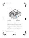
After removing the old system board, lower the new system board into the
chassis, aligning the I/O ports on the system board with the I/O connector
openings on the back panel of the chassis.
2
Using a #2 Phillips screwdriver, install the six screws on the system board
that secure it to the chassis. See Figure 6-2.
3
Using a #2 Phillips screwdriver, attach the processor heat sink pivot
mount to the system board. See Figure 6-2.
NOTICE: To prevent damaging the processor, clean the heat sink to remove any
thermal grease and then apply fresh thermal grease to the processor before
installing the heat sink.
4
Replace the processor, and the heat sink and shroud assembly. See
"Replacing the Processor" on page 82.
book.book Page 101 Wednesday, April 15, 2009 8:47 PM