


Installing System Components 83
NOTICE: Use caution when removing and installing the processor. Damaging the
processor socket connectors can damage the system board.
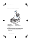
4
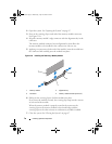
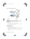
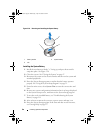
Carefully set the processor in the processor frame. Ensure that the notched
edge of the processor fits securely over the matching tab on the processor
frame. Do not press down on the processor. If the processor is seated
correctly, it should fit snugly in the socket frame. See Figure 3-22.
5
Lower the retention latch onto the processor, and then rotate the release
lever latch back toward the system board until it snaps into place.
6
Clean the thermal grease from the bottom of the heat sink.
NOTICE: Ensure that you apply new thermal grease. Applying new thermal grease
is critical to ensuring proper thermal bonding as well as optimal processor
operation.
7
Apply new thermal grease to the top of the processor.
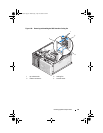
8
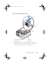
Place the heat sink assembly back onto the heat sink assembly bracket and
tilt the heat sink assembly down on the system board. See Figure 3-21.
9
Align the two captive screws properly with the system board, then tighten
them to secure the heat sink assembly to the system board.
10
Close the system. See "Closing the System" on page 47.
11
Reconnect the system to the electrical outlet, and turn on the system and
attached peripherals.
Cooling Fans
The system contains two cooling fans, one for the processor and one for the
card cage. Each contains a shroud that is part of the cooling fan assembly.
The fan and shroud are replaced as a unit.
NOTE: If you are removing the larger processor cooling fan, you must first remove
the heat sink and shroud assembly. See "Removing the Processor" on page 79
(however, do not remove the processor) and Figure 3-24.
book.book Page 83 Wednesday, April 15, 2009 8:47 PM