


Installing System Components 99
2
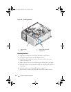
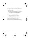
Secure the I/O panel assembly by replacing the screw. See Figure 3-30.
3
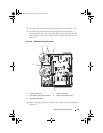
Secure the I/O panel ribbon cable through the clips beneath the 3.5
optional diskette drive and on the side of the power supply shroud, and
connect the I/O panel ribbon cable to the new I/O panel connector. See
Figure 3-31.
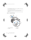
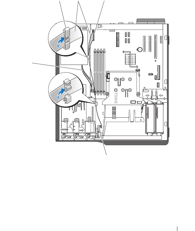
Figure 3-31. Cabling the I/O Panel Assembly
4
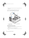
Replace the large processor cooling fan. See "Replacing the Cooling Fans"
on page 86.
1 I/O panel connector 2 I/O panel assembly
3 4-pin power cable to system board 4 cable clip on power supply
5 I/O panel ribbon cable
4
2
5
1
3
book.book Page 99 Wednesday, April 15, 2009 8:47 PM