


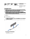
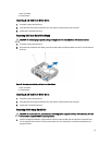
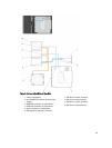

2. optical drive blank lock
Installing The Slim Optical Drive Blank
CAUTION: Many repairs may only be done by a certified service technician. You should only perform
troubleshooting and simple repairs as authorized in your product documentation, or as directed by the online or
telephone service and support team. Damage due to servicing that is not authorized by Dell is not covered by your
warranty. Read and follow the safety instructions that came with the product.
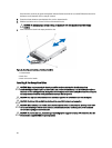
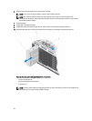
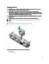
1. Align the slim optical drive blank with the slim optical drive bay.
2. Slide the optical drive blank into the optical drive bay until the lock clicks into place.
3. Close the system.
4. If applicable, install the front bezel.
Optical Drives And Tape Drives
Your system supports one of the following configurations.
Systems with up to eight 3.5 inch hard drives and sixteen 2.5 inch hard drives support:
• Up to two SATA half height DVD-ROM or DVD R/W drive plus one SAS interface tape drive or
• Up to one SATA half height DVD-ROM or DVD R/W drive plus one internal RD1000 drive plus one SAS interface
tape drive
Systems with up to 12 hard drives support:
• Up to one SATA half height DVD-ROM or DVD R/W drive or
• Up to one internal RD1000 drive or
• Up to one SAS interface tape drive
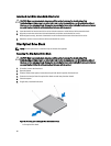
Systems with up to 32 hard drives support one slim optical drive. Tape drives are not supported.
Removing The Optical Drive Or Tape Drive
CAUTION: Many repairs may only be done by a certified service technician. You should only perform
troubleshooting and simple repairs as authorized in your product documentation, or as directed by the online or
telephone service and support team. Damage due to servicing that is not authorized by Dell is not covered by your
warranty. Read and follow the safety instructions that came with the product.
1. If installed, remove the front bezel.
2. Turn off the system, including any attached peripherals, and disconnect the system from the electrical outlet and
peripherals.
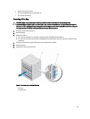
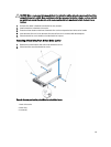
NOTE: For systems installed with the wheel assembly, ensure that you lay the system on a sturdy, stable
surface with the wheel assembly extending off the edge of the surface.
3. Open the system.
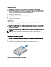
4. Disconnect the power and data cable from the back of the drive.
Note the routing of the power and data cable inside the chassis as you remove them from the system board and the
drive. You must route these cables properly when you replace them to prevent them from being pinched or
crimped.
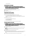
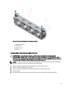
5. To remove the drive, push the release latch in the direction of the arrow indicated in the figure.
61