


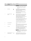


Item Indicator, button, or
connector
Icon Description
Integrated Dell Remote Access Controller User's
Guide at dell.com/esmmanuals.
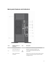
This port is USB 2.0-compliant
9 VGA connector Allows you to connect a VGA display to the
system.
NOTE: The VGA connector is available only in
the rack-mode configuration of your system.
For information on converting your system
from tower to the rack mode, see Preparing a
system for conversion from tower mode to
rack mode .
10 USB connector Allows you to connect USB devices to the system.
This port is USB 3.0-compliant.
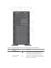
11 Optical drive or tape-
drive bay
Allows you to install optical drives or tape drives.
For more information on supported optical drives
and tape drives, see Optical drives and tape drives.
12, 14, 15 Physical drives 3.5 inch hard drives, 2.5 inch hard drives, and PCIe
SSDs
13 Flex Bay Supports up to four PCIe SSDs or up to sixteen 2.5
inch hard drives depending on the system
configuration.
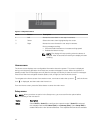
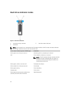
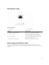
LCD panel features
The LCD panel of your system provides system information and status and error messages to indicate if
the system is operating correctly or if the system needs attention. For more information on error
messages, see the Dell Event and Error Messages Reference Guide at dell.com/esmmanuals.
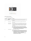
• The LCD backlight lights blue during normal operating conditions and lights amber to indicate an
error condition.
• The LCD backlight is off when the system is in standby mode and can be turned on by pressing either
the Select, Left, or Right button on the LCD panel.
• The LCD backlight remains off if LCD messaging is turned off through the iDRAC utility, the LCD
panel, or other tools.
13