


Chapter 5 Control Block and Status Block|ScrEdit Software User Manual
Revision Apr. 30th, 2007, 2007PDD23000002 5-9
5.2 Status Block
For two-way communication and display screen between DOP series and all brands’ PLC, it needs to input
starting address of response register in status block. The status block in DOP series HMI is a continuous
data block, such as Dm=D10 (length is 8 WORDs = D10-D17). When the control block size is set to 0, the
control block function is disabled. If the control block function is disabled, the status block function is also
disabled. When the status block function is enabled, the external controller, i.e. PLC can know the status of
HMI by writing the setting in status block. But, please note that the address of control block and status block
cannot be the same.
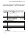
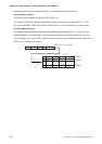
The function and explanation of each WORD are listed below. (In the following table, we assume that the
user will use a Delta PLC, so the available starting addresses in control block are Dm ~ Dm+7 (D10 ~ D17).)
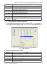
Word Number Register
0 Status Register for General Control (GCSR) Dm (D10)
1 Status Register for Screen Number (SNSR) Dm+1 (D11)
2 Status Register for Curve Control (CCSR) Dm+2 (D12)
3 Status Register for Sampling History Buffer (HSSR) Dm+3 (D13)
4 Status Register for Clearing History Buffer (HCSR) Dm+4 (D14)
5 Recipe Status Register (RESR) Dm+5 (D15)
6 Status Register for Recipe Number (RBSR) Dm+6 (D16)
7 Status Register 2 for General Control (GCSR2) Dm+7 (D17)
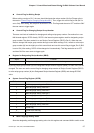
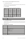
Status Register for General Control (GCSR)
Bit Number Function
0 Screen Switch Status
1~2 Reserved
3 Clear Status of Alarm Buffer
4 Clear Status of Alarm Counter
5-7 Reserved
8 User Level (Bit0)
9 User Level (Bit1)
10 User Level (Bit2)
11~15 Reserved
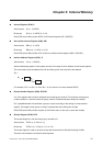
Screen Switch Status
When the screen is switched, the Bit will be set to ON. After screen switch is completed, the Bit will be
OFF.
Clear Status of Alarm Buffer
When HMI clear the alarm buffer (clear status of alarm buffer function is enabled), the Bit will be set to
ON. After this function is completed, the Bit will be OFF.