


Appendix A Specifications and Installation|ScrEdit Software User Manual
A-10 Revision Apr. 30th, 2007, 2007PDD23000002
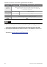
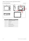
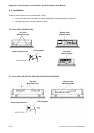
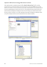
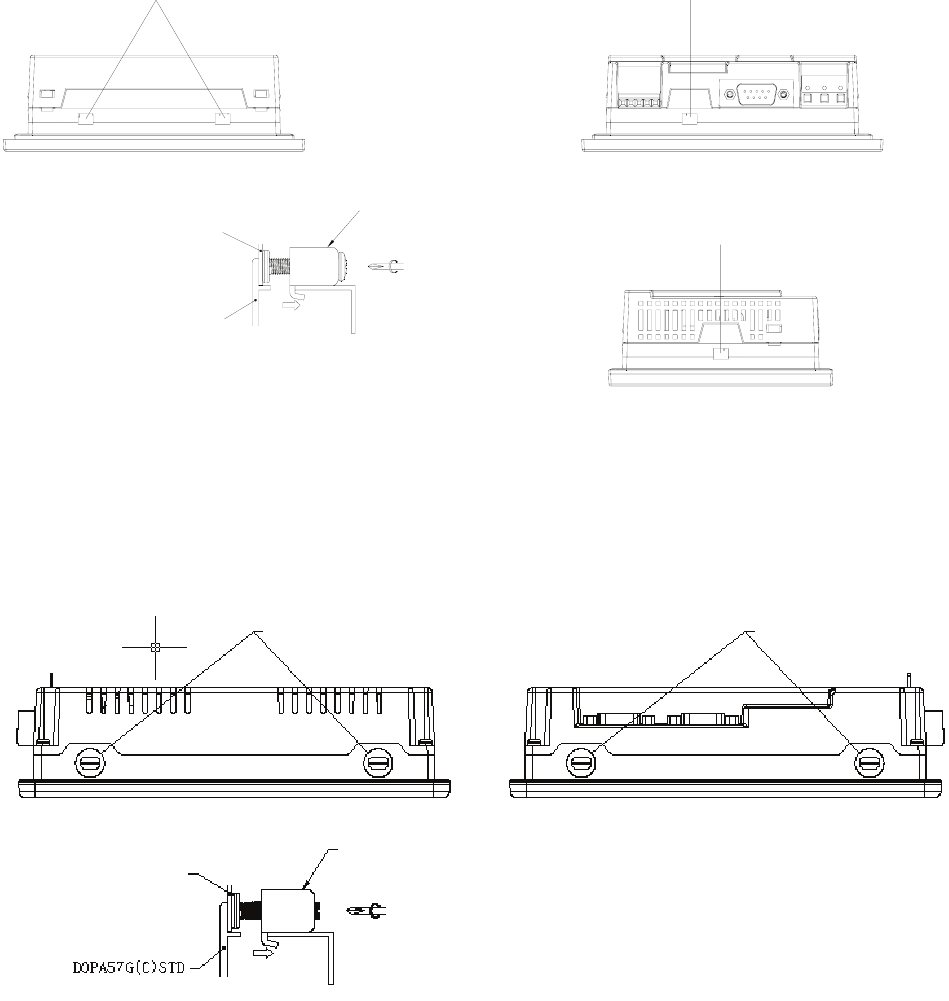
A.3 Installation
Install the fixed support from the internal side of HMI.
1. Do not turn the screw more than its torque specification to avoid damage to plastic box.
2. Damage may occur if torque exceeds 0.7N.M
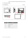
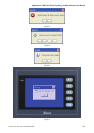
3.8” Panel (DOP-AS38BSTD(-W))
DOPAS38BSTD(-W)
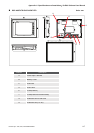
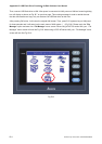
5.7” Panel (DOP-A(E)57GSTD, DOP-A(E)57CSTD,DOP-A(E)57BSTD)
Top View
Mounting holes
Bottom View
Mounting holes
Fixed support
Snap-in panel mount
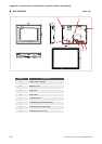
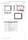
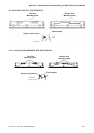
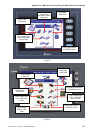
Top View
Mounting holes
Bottom View
Mounting hole
Fixed support
Snap-in panel mount
Side View
Mounting hole