


Chapter 2 Creating and Editing Screens|ScrEdit Software User Manual
2-80 Revision Apr. 30th, 2007, 2007PDD23000002
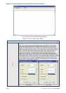
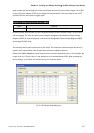
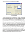
Fig. 2.8.29 Input dialog box
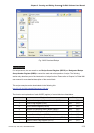
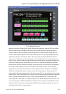
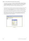
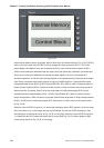
The definition of Delta HMI recipe register RCP is described as follows. In Fig. 2.8.26, the length of example
recipe is set to 6 and the group of example recipe is set to 7. However, HMI actually create recipe registers
(RCP0 ~ RCP15) which the length is 6 but the group is 8. As the user can see in the Fig. 2.8.30, RCP0 ~
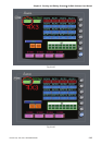
RCP5 is defined as recipe buffer area and RCP6 ~ RCP17 is the actual recipe storage area. The function of
recipe buffer area is for the user to put the desired change recipe data no matter execute Write Recipe or
Read Recipe operation. When the user want to change recipe data, the user have to use RCPNO or RBIR
these two registers. In the example shown in Fig. 2.8.30, when RCPNO is set to 2, it means that the using
recipe group is 2
nd
group. At this time, HMI will move the data of 2
nd
group and put them in the recipe buffer
area (RCP0 ~ RCP5). Besides using internal memory address (RCPG and RCPNO), the user also can enter
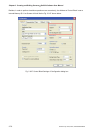
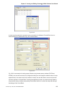
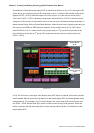
into Configuration dialog box and change the address value of recipe register directly. Since the example
control block address is set to $0, the user should use $6 RBIR, i.e. Designated Recipe Group Number
Register to designate recipe group and press Change Group ($5.0) button to designate the desired using
recipe group. When Write Recipe ($5.2) button is pressed, Write Recipe operation will be enabled. HMI will
write the recipe data from HMI recipe register RCP into the designated recipe storage address ($220 ~
$225). The example in Fig. 2.8.30 just displays the screen when HMI write the recipe data into $220 ~ $225.
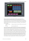
Read Recipe ($5.1) button is used to execute read recipe operation. When this button is pressed, HMI will
read recipe data of recipe storage address ($220 ~ $225) back to HMI recipe register RCP.