


12
Chapter 2 Introduction
A list of product variants to which this manual applies can be found in Section 2.11, “Applicability” on
page 14.
2.3 Power Supplies
An SS7G21 or SS7G22 product can be ordered with one of the following:
• AC-input Power Supply Cage (SS7G21A, SS7G22A)
• DC-input Power Supply Cage (SS7G21D, SS7G22D)
The Power Supply Cage, which is mounted towards the left rear of the chassis, contains the Power Supply
Modules. Both the AC and DC-input Power Supply Cage may contain up to two Power Supply Modules and
can be configured as follows:
• One Power Supply Module installed (this is the factory standard setting). Units configured in this manner
can supply a fully loaded product, but do not provide dual redundancy. The second position contains a
filler module.
• Two Power Supply Modules installed. Units configured in this manner are dual redundant. In the event of
a failure of any one Power Supply Module, the operation of the product is unaffected.
When the product is configured with two Power Supply Modules, the hot-swap feature allows the user to
replace a failed module without interrupting system functionality.
Caution: The Power Supply Modules used in the AC-input Power Supply Cage can not be used in the DC-
input Power Supply Cage. Similarly, the Power Supply Modules used in the DC-input Power
Supply Cage can not be used in the AC-input Power Supply Cage. The correct product variant
must be specified at time of ordering, see Chapter 12, “Part Number Reference”.
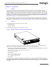
2.4 Server Board
The chassis incorporates a Server Board incorporating dual Intel Xeon processors with 512 KB L2 cache and
1 GB DRAM DIMM memory. The Server Board has a Riser Board, which supports the fitting of up to three
full-length PCI SS7 Signaling Boards. See Section 2.7, “SS7 Signaling Boards” on page 12 for more
information on the types of SS7 Signaling Boards that are installed.
2.5 Hard Disk Drive
As standard, a Hard Disk Drive (HDD) is installed in a drive bay in the front of the chassis, accessible by
removing the front bezel of the product. A spare assembly is available for the HDD, see Chapter 12, “Part
Number Reference”.
2.6 CD-ROM Drive
A CD-ROM drive is accessible at the front panel, and may be used for loading software updates.
2.7 SS7 Signaling Boards
The SS7G21 and SS7G22 use intelligent multi-port interface boards with one or more on-board signaling
processors for the processing of SS7 signaling links. The SS7 Signaling Boards are full-size PCI form factor
boards that occupy one, two, or three board positions in a Riser Board mounted on the Server Board. The
SS7 Signaling Boards each provide four (or two) primary rate telecommunications (PCM) interfaces, each
being individually configured at run-time under software control to operate as a T1 or E1 interface with
selectable line code and frame format. For SS7 Signaling Boards with two PCM interfaces, there are also two
synchronous V.11 (V.35 compatible) serial interfaces, on a shared connector. See Section 6.5, “SS7 Serial
Interface Ports” on page 36 and Appendix A for more information.
The number of SS7 signaling links that can be terminated by an SS7 Signaling Board depends on the board
type as described below. Signaling links may be presented either as a timeslot on an external PCM interface,
or as a synchronous V.11 serial interface when provided by the board. Signaling links can operate at 64kb/s,
56kb/s or 48kb/s. The SS7 Signaling Boards also support configurable clock recovery priorities with
automatic switching to a new clock source on failure, and automatic restoration on recovery of the failed
clock source.