


18
Chapter 3 Product Specification
alarms is given in the appropriate SS7G2x <Operating Mode> User Manual. Section 2.10, “Related
Information” on page 13 lists the various user manuals.
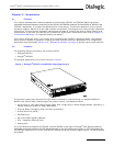
• MNR Alarm LED (amber)
When lit continuously, indicates the presence of a minor fault. A minor fault is an error or event that is
detected by the unit but has little or no impact on the actual unit’s operation. The full list of minor alarms
is given in the appropriate SS7G2x <Operating Mode> User Manual. Section 2.10, “Related Information”
on page 13 lists the various user manuals.
• PWR Alarm LED (amber)
When lit continuously, indicates the presence of a power fault. The power alarm relay is engaged.
• 0 Activity/Fault LED (green/amber)
Indicates SCSI Hard Disk Drive (HDD) 0 activity when green, or a SCSI HDD 0 fault when amber.
• 1 Activity/Fault LED (green/amber)
Indicates SCSI Hard Disk Drive (HDD) 1 activity when green, or a SCSI HDD 1 fault when amber.
• ON LED (green)
When lit continuously, indicates the presence of DC power in the product. The LED goes out when the
power is turned off or when the power source is disrupted.
• NIC Activity LED (green)
Indicates activity on either network interface, ENET1 or ENET2.
• ID LED (white)
This white LED is used in conjunction with the ID switch, and back panel ID LED (blue), to provide a
service technician facility to highlight a specific SS7G21 or SS7G22 in a rack of similar units. The LEDs
can be illuminated and deactivated by the ID switch (see description below).
• ID switch
In conjunction with the front and back panel ID LEDs, this switch provides a service technician facility to
highlight a specific SS7G21 or SS7G22 in a rack of similar units. Pressing the ID switch toggles the front
and back panel ID LEDs between the illuminated and deactivated states.
Back Panel
• ID LED (blue, inside grill)
This blue LED, visible through the grill at the back of the SS7G21 and SS7G22, is used in conjunction
with the front panel ID Switch and ID LED (white), to provide a service technician facility to highlight a
specific SS7G21 or SS7G22 in a rack of similar units. The LEDs can be illuminated and deactivated by the
ID switch (see description above). See Figure 4, “Back Panel Connectors and Indicators” on page 33 for
the location of the blue LED.
Visual Indicators on the Ethernet Ports
The Ethernet ports have built-in indictors that provide visual indications of link activity and port speed. See
Section 6.6, “Ethernet Interfaces” on page 38 for more information.
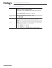
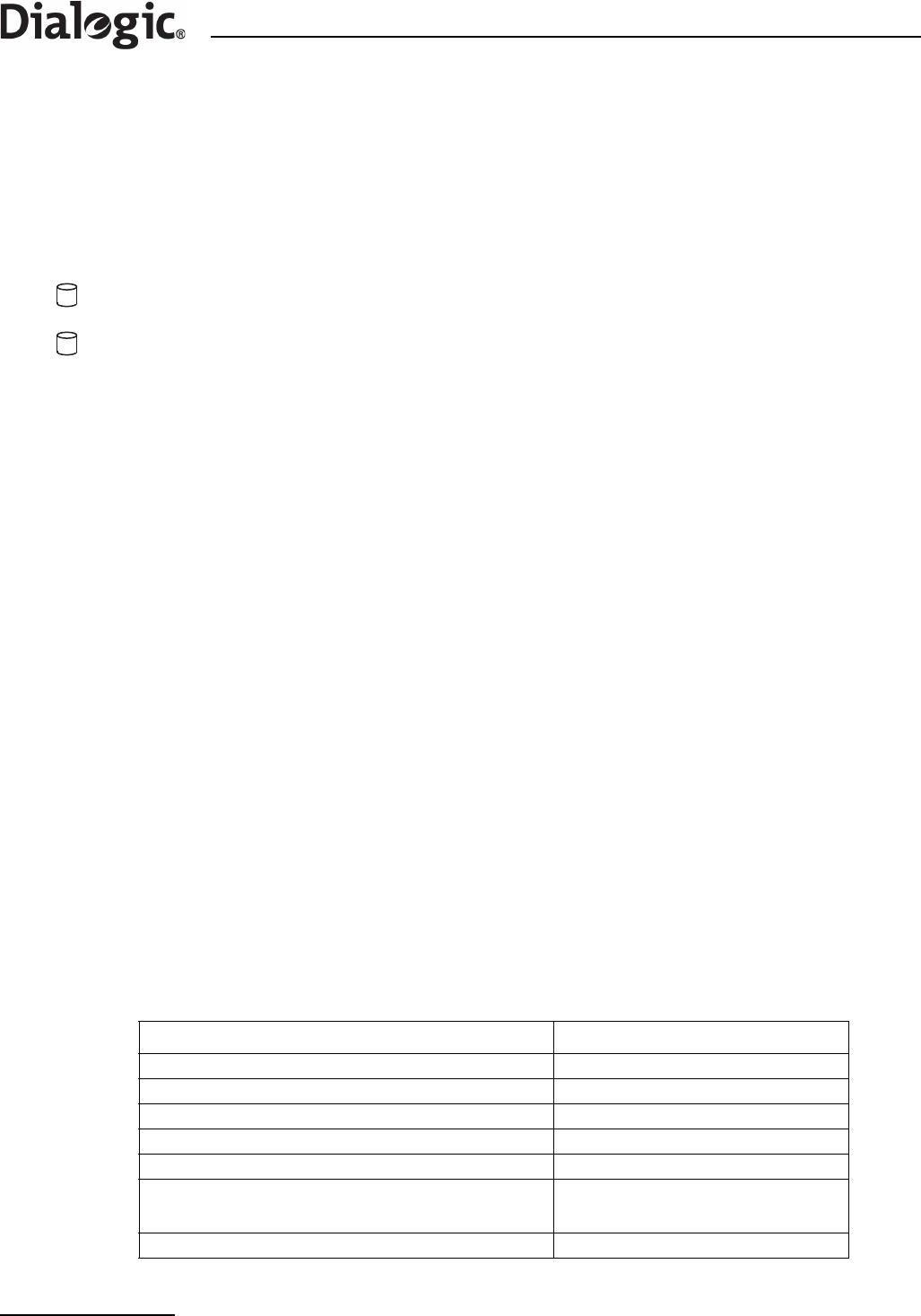
Visual Indicator on the Power Supply Module
A single bi-color LED, on the back of each module, provides power supply status as described in the following
table.
Power Supply Condition LED Indication and Color
No input power to all Power Supply Modules Off
No input power to this Power Supply Module only Amber
Input power present/Only standby outputs on Green, Blinking
Power supply DC outputs on and OK Green
Current limit; AC modules only Amber
Alert condition; DC modules only
NOTE: “Alert condition” means that the module is functional,
but the input voltage is close to operational limits.
Amber
Power supply failure (OTP, OCP, OVP, UV) Amber