


32
Chapter 5 Hardware Description
5.2 Front Panel
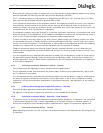
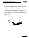
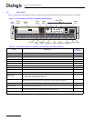
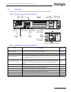
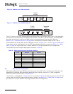
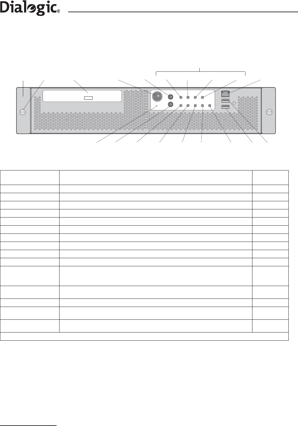
Figure 3 shows the front panel controls, indicators and switches and Table 3 summarizes their functions.
Figure 3. Front Panel Controls, Indicators and Switches
Table 3. Front Panel Control, Indicator and Switch Function Summary
Feature Description
More
Information
Front bezel Front panel cover N/A
Thumb screws Secure the front bezel to the chassis N/A
Peripheral drive CD-ROM Drive N/A
Power switch Toggles the product power on and off Section 3.9
Reset switch Reboots and initializes the product Section 3.9
CRT Alarm LED † Critical Alarm LED (amber) Section 3.9
MJR Alarm LED † Major Alarm LED (amber) Section 3.9
MNR Alarm LED † Minor Alarm LED (amber) Section 3.9
PWR Alarm LED † Power Alarm LED (amber) Section 3.9
USB 2, USB3 Standard USB ports N/A
Disk 0, Disk 1
Activity LEDs
Activity LEDs for Hard Disk Drives (HDDs) that indicate one of the following:
• When green, indicates SCSI HDD activity
• When amber, indicates SCSI HDD fault
Section 3.9
ON Power LED
Power LED (green). When lit continuously, indicates the presence of DC power in the unit.
The LED goes out when the power is turned off or the power source is disrupted.
Section 3.9
NIC Activity LED An activity LED (green). Indicates activity on either ENET 1 or ENET 2. Section 3.9
System ID LED
A system ID LED (white) that can be used to highlight the unit in a rack of units. The LED
can be activated via the ID switch.
Section 3.9
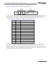
ID switch
Toggles the white System ID LED on the front panel and a blue system ID LED inside the grill
on the back panel. See Figure 4 for the location of the blue LED.
Section 3.9
† See Section 3.9, “Controls and Indicators” on page 17 for more information on alarm indications.
Power
Switch
Reset
Switch
CRT MJR MNR PWR
Alarm LEDs
Unused
Port
Not Used ID
Switch
System ID
LED
NIC
Activity LED
ON
LED
Disk 1
Activity LED
Disk 0
Activity LED
USB 3
Front
Bezel
CDROM
Drive
Thumb
Screws
USB 2