


49
Dialogic
®
SS7G21 and SS7G22 Signaling Servers Hardware Manual Issue 7
Chapter 9: Product Installation and Hot-Swap Actions
This chapter describes actions that must be performed by a qualified service technician, but which do not
require the removal of the Top Cover of the product. Before commencing these procedures, read Chapter 7,
“Warnings and Cautions” in Part II of this manual.
Do not proceed to remove the Top Cover without consulting Section 10.1, “Safety: Before Removing the Top
Cover” on page 59 and Section 10.2, “Warnings and Cautions: Working Inside the Product” on page 59.
9.1 Installation Overview
Installation of a Dialogic
®
SS7G21 or SS7G22 product involves the following tasks performed in the order
shown. References to more detailed task descriptions are provided where appropriate.
To install an SS7G21 or SS7G22 unit, proceed as follows:
1. Read all warnings and cautions. See Chapter 7, “Warnings and Cautions” for details.
2. Choose the right product to suit the application taking into account the number and type of interface
ports, the link processing capability, and whether the product needs to be AC- or DC-powered. See
Section 12, “Part Number Reference” on page 79 for more information on the available product variants.
3. Install any hardware options purchased, for example, an extra PSU module (see Section 9.2, “Power
Supply Related Actions” on page 50) or mounting rails for the product (see Section 5.4, “Rack Mounting
Options” on page 34 for more information).
4. Physically install the product in an equipment rack or as a free standing unit.
5. Connect the product to ground:
— When installing a DC-powered product, see Section 9.2.1, “Safety Ground Studs, Conductor
Installation” on page 51.
— When installing an AC-powered product, the ground connection and power connection are part of the
same operation. See step 6 below.
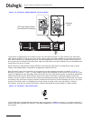
6. Connect the power source:
— When installing a DC-powered product for the first time, see Section 9.2.2, “DC Power Supply
Module, Initial Connections” on page 51. When replacing a product, see Section 9.2.3, “DC Power
Supply Module, Transferring Connections” on page 53.
— When installing an AC-powered product, see Section 6.3, “AC Power Input” on page 35.
In either case, ensure that the chosen power source meets the relevant requirements for “MAINS AC/DC
POWER DISCONNECT” and “OVERCURRENT PROTECTION” as described in Chapter 7, “Warnings and
Cautions”.
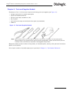
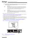
7. Connect line interface, Ethernet interface, and alarm cables. See Chapter 6, “Interfaces” for connector
details and pinout information for the various interfaces.
— To ensure that you avoid EMC problems with the installation, comply with the instructions and advice
given in Section 4.3.2, “EMC” on page 28.
— For safety and operational aspects affecting network connections, comply with the advice given in
Section 4.3.3, “Telecommunications” on page 28 and any region-specific requirements in
Section 4.2.3, “FCC Part 68 Statement - USA” on page 26,
Section 4.2.4, “Telecommunications Attachment Notice - Canada” on page 27,
Section 4.2.6, “Telecommunications Notice - Australia / New Zealand” on page 27,
Section 4.2.7, “Telecommunications Notice - Taiwan” on page 27.
8. Power up the product.
9. Complete the following software and configuration steps, all of which are fully described in the
appropriate SS7G2x <Operating Mode> User Manual. Section 2.10, “Related Information” on page 13
lists the various user manuals.
— Check whether a software download and upgrade is required.
— Install optional software licenses.
— Set the IP addresses of the unit.
— Enable the selected Operating Mode (SIU, DSC or SGW).
Note: The SIU Operating Mode is enabled by default.