


64
Chapter 10 Working Inside the Product
Note: If only two SS7HDP Signaling Boards are installed, then the middle position (No.2) should remain
empty.
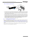
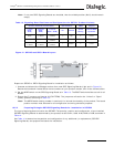
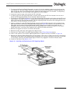
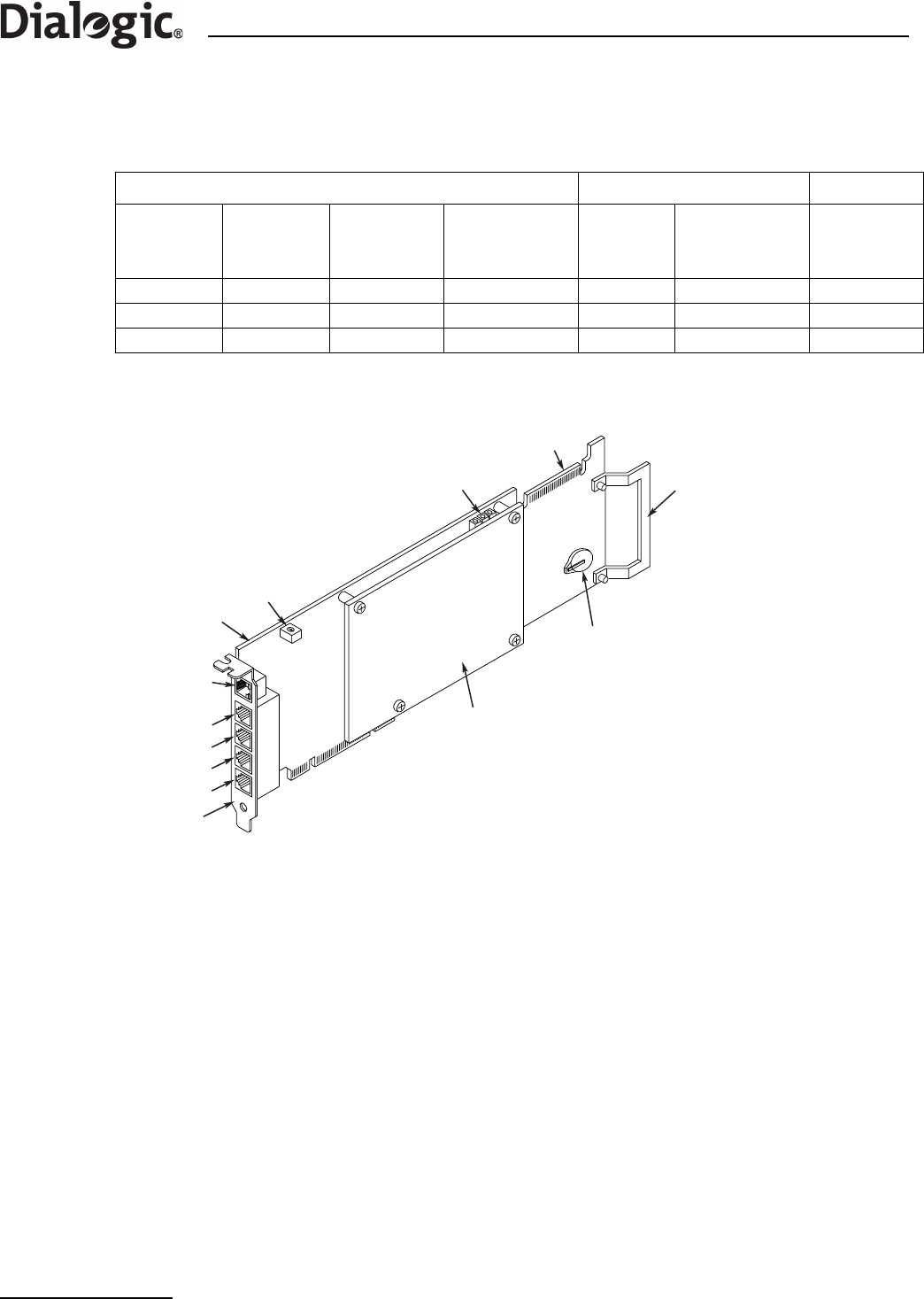
Figure 22. Dialogic
®
SS7HDP Board Layout
Prepare an SS7HDP Signaling Board for installation as follows:
1. Unscrew and discard the ISA edge retainer from a new SS7HDP Signaling Board (right end in Figure 22).
Record the board and software License Button serial numbers on your product records, then fit the
Licence Button.
2. Set the ADDR switch on the SS7HDP Signaling Board as in Table 14.
Note: The ADDR switch setting number is used only for internal functionality of the product. The board
position number must be used for all configuration and wiring schedule purposes.
10.5.3 Installing or Replacing an SS7 Signaling Board
Installation of extra SS7 Signaling Boards in positions No. 2 and No. 3, or replacement of a board in any
position, follow basically the same steps, but ensure that in each case the SS7 Signaling Board fitted is
correctly configured as identified in Table 13, “Signaling Board Positions and Configurations for SS7G21
Product Variants” on page 63 and Table 14, “Signaling Board Positions and Configurations for Dialogic
®
SS7G22 Product Variants” on page 64.
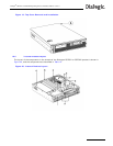
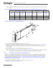
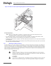
Install/Replace an SS7 Signaling Board as follows, referring to Figure 23:
1. Remove the Top Cover. See Section 10.3.
Table 14. Signaling Board Positions and Configurations for Dialogic
®
SS7G22 Product Variants
Quantity of Boards (Variant Suffix) Board Position ADDR
0 boards
(00W)
1 board
(H1W)
2 boards
(H2W)
3 boards
(H3W)
No. Position
Switch
Setting
Blank Blank SS7HDP SS7HDP 3 Top 2
Blank Blank Blank SS7HDP 2 Middle 1
Blank SS7HDP SS7HDP SS7HDP 1 Bottom 0
Port L1
Daughter
Board
H.100 Edge
Connector
Base
Board
Port L2
Port L3
Port L4
ISA Edge
Retainer
License
Button
Holder
LEDs
ADDR
ENET
Port
End
Bracket