


37
Dialogic
®
SS7G21 and SS7G22 Signaling Servers Hardware Manual Issue 7
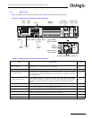
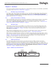
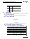
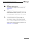
Figure 8. SS7 Serial Interface Connector (Aux on SPCI2S)
The SS7 serial interface ports on the SPCI2S are designated as SELV. Install the ferrite clamp(s), provided
with this product, on each SS7 serial interface port cable, close to the connector backshell, to ensure the
EMC performance of the product. The connector pinout and signal assignment is given in Table 6.
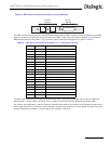
The SS7 serial interface ports may be clocked either by an internally generated clock or by an externally
applied clock. In both cases, the same clock is used for both the Transmit data and the Receive data.
For internal clock operation, use the Transmit clock pins and make no connection to the Receive clock pins on
the D-type connector. For external clock operation, connect the clock source to the Receive clock pins on the
D-type connector and make no connection to the Transmit clock pins.
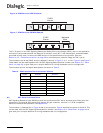
T1/E1
Ports
V.11
Ports
L4
L3
AUX
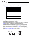
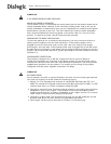
Table 6. SS7 Serial Interface Ports (Dual V.11) Connector Pinouts
Pin No Direction Function
1 Chassis ground
2 Output V.11 Transmit inverted clock Port B
3 Output V.11 Transmit clock Port B
4 Output V.11 Transmit inverted data Port B
5 Output V.11 Transmit true data Port B
6 Input V.11 Receive inverted clock Port B
7 Input V.11 Receive clock Port B
8 Input V.11 Receive inverted data Port B
9 Input V.11 Receive true data Port B
10 Signal ground
11 to 18 No connection
19 Output V.11 Transmit inverted clock Port A
20 Output V.11 Transmit clock Port A
21 Output V.11 Transmit inverted data Port A
22 Output V.11 Transmit true data Port A
23 Input V.11 Receive inverted clock Port A
24 Input V.11 Receive clock Port A
25 Input V.11 Receive inverted data Port A
26 Input V.11 Receive true data Port A