


COPYRIGHT © 2006 MERIT INDUSTRIES, INC.
Ethernet Cable Pin Out and Instructions
Part of the jukebox installation process requires making a custom Ethernet cable, as the
cable length will be unique for each location. This cable will be run between the jukebox and
router. This customization will save costly cable and result in a neater installation process.
To install the cable you will need:
• Category 5 UTP cable (eight-conductor data cable with 4 pairs unshielded twisted wires)
• RJ-45 plugs and a Telco crimping tool
• Cable testing device (optional but recommended)
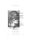
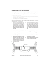
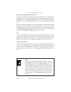
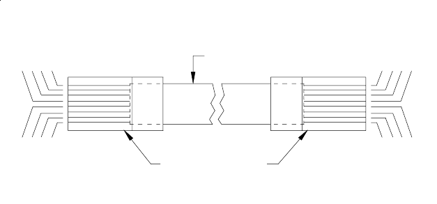
Refer to the following directions to make a “straight through” cable where pin 1 on one end
corresponds to pin 1 on the other end.
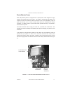
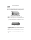
FIGURE 2-4 - ETHERNET CABLE
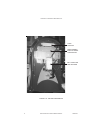
5. Hold the RJ-45 Ethernet plug head in
your other hand with the hook faced
down. Slide the wires into the connec-
tor head. Make sure that the wires stay
in the correct order and fit into their own
slots. All wires must hit the end of the
plug.
6. Slide the connector head into the RJ-
45 crimping tool and squeeze down
hard. Look at the side of the plug and
check that the metal contacts went into
the wires. If not, squeeze down again.
7. Repeat the above steps for the other
end (same pin out scheme).
8. Use the cable testing device to ensure
that the cable was built correctly.
1. Cut back 1" of the outer, plastic cover-
ing to reveal 4 twisted pairs and some
insulation material. If you partially cut
some of the wires, cut them all off and
start over. Each pair is a solid color wire
twisted with a striped white and same
color wire.
2. Cut out the insulation material to the bot-
tom of the removed plastic.
3. Untwist each pair no more than 1 cm
and lay them flat together pinched be-
tween your fingers in the same order
as shown in Figure 2-4.
4. Hold the 8 wires together and cut them
at the top to make them all the same
length. The length of the wires should
be slightly shorter than the length of the
connector so that the cut plastic just fits
inside the connector.
PM0599-03 MOD BOX INSTALLATION & OWNER’S MANUAL 20
B
R
O
W
N
W
H
I
T
E
/
B
R
O
W
N
G
R
E
E
N
W
H
I
T
E
/
B
L
U
E
B
L
U
E
OR
A
N
G
E
W
H
I
T
E
/
G
R
E
E
N
W
H
I
T
E
/
OR
A
N
G
E
B
L
U
E
W
H
I
T
E
/
G
R
E
E
N
O
R
A
N
G
E
W
H
I
T
E
/
OR
A
N
G
E
W
H
I
T
E
/
B
L
U
E
W
H
I
T
E
/
B
R
O
W
N
G
R
E
E
N
B
R
O
W
N
INSULATION
RJ-45 PLUGS WITH THE
LOCKING TAB ON THE
OPPOSITE SIDE