


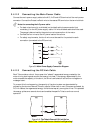

Keep the motor wires as far away as possible from the feedback, control and
communication cables.
Ensure that in normal operating conditions, the shielded wires and drain carry no current.
The only time these conductors carry current is under abnormal conditions, when
electrical equipment has become a potential shock or fire hazard while conducting
external EMI interferences directly to ground, in order to prevent them from affecting the
drive. Failing to meet this requirement can result in drive/controller/host failure.
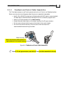
After completing the wiring, carefully inspect all wires to ensure tightness, good solder
joints and general safety.
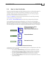
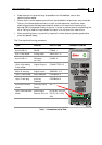
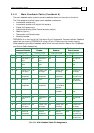
The Tuba has the following connectors:
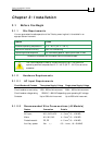
Type
Function
Port on Tuba Connector Location
8-pin RJ-45 x 2 RS-232 COMM. 1
9 pin D-sub socket Analog Input ANALOG I/O
8-pin RJ-45 x 2 CANopen
(In/Out)
COMM. 2
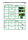
15-pin high-density
D-sub socket
Digital Outputs COMMITTED I/O
25-pin D-sub plug Digital Inputs GENERAL I/O
15-pin D-sub socket Main Feedback FEEDBACK A
15-pin D-sub plug Auxiliary
Feedback
FEEDBACK B
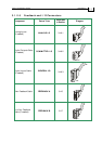
2-pin terminal strip
Molex
Auxiliary Power
Supply
24v +, -
10-pin terminal block
Molex
Mains, Motor
Power & DC Link
B1, B2, M1, M2, M3,
PE, PE, AC1, AC2,
AC3
Table 3-1: Connectors on the Tuba
Tuba Installation Guide Installation
MAN-TUBIG (Ver. 1.3)
3-8