


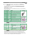
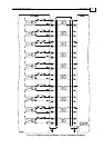
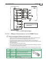
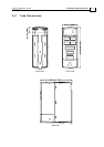

Figure 3-30: RS-232 Connection Diagram
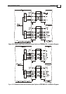
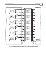
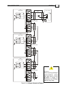
3.4.9.2 CANopen Communication (on the COMM.2 Ports)
Notes for connecting the CANopen communication cable:
Use 26 or 28 AWG twisted pair shielded cables. For best results, the shield should
have aluminum foil and covered by copper braid with a drain wire
Connect the shield to the ground of the host (PC). Usually, this connection is
soldered internally inside the connector at the PC end. You can use the drain wire to
facilitate connection.
The male RJ plug must have a shield cover.
Ensure that the shield of the cable is connected to the shield of the RJ plug. The drain
wire can be used to facilitate the connection.
Connect a termination 120-ohm resistor at each of the two ends of the network cable.
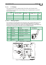
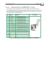
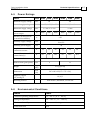
Pin Signal Function Pin Position
1 CAN_H CAN_H busline (dominant high)
2 CAN_L CAN_L busline (dominant low)
3 CAN_GND CAN ground
4, 5, 8 — —
6 CAN_SHLD Shield, connected to the RJ plug cover
7 CAN_GND CAN Ground
Table 3-14: CANopen Cable - Pin Assignments
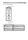
Only one RS-232 port can be
used at a time.
Tuba Installation Guide Installation
MAN-TUBIG (Ver. 1.3)
3-39