


3.4.7 Auxiliary Feedback (FEEDBACK B)
When using one of the auxiliary feedback options, the relevant functionality of FEEDBACK B
ports are software selected for that option. Refer to the Tuba Command Reference Manual for
detailed information about FEEDBACK B setup.
3.4.7.1 Main Encoder Buffered Outputs or Emulated Encoder
Outputs Option on FEEDBACK B (YA[4]=4)
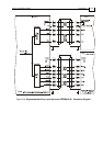
Through FEEDBACK B (Ports B1 and B2) the Tuba can provide two simultaneous
buffered main, or emulated, encoder signals to other controllers or drives. This option
can be used when:
The Tuba is used as a current amplifier to provide position data to the position
controller.
The Tuba is used in velocity mode, to provide position data to the position controller.
The Tuba is used as a master in Follower or ECAM mode.
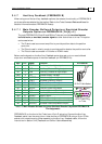
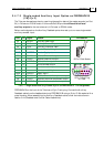
Below are the signals on the Auxiliary Feedback ports when set up to run as a buffered
outputs or emulated outputs of the main feedback (on FEEDBACK A):
Port Pin Signal Function Pin Position
B1 1 INDEX Auxiliary index high output
B1 2 CHB Auxiliary Channel B high output
B1 3 CHA Auxiliary Channel A high output
PWR 4 +5V Encoder supply voltage
PWR 5 SUPRET Encoder supply voltage return
B2 6 CHAO Buffered Channel A output
B2 7 CHBO Buffered Channel B output
B2 8 INDEXO Buffered Index output
CO
R
0
1
6
A
15 Pin D-Sub Socket
B1 9 INDEX- Auxiliary Index low output
B1 10 CHB- Auxiliary Channel B low output
B1 11 CHA- Auxiliary Channel A low output
PWR 12 SUPRET Supply return
B2 13 CHAO- Buffered Channel A complement output
B2 14 CHBO- Buffered Channel B complement output
B2 15 INDEXO- Buffered Index complement output
8
15
1
9
Port B1 Power
Port B2
15 Pin D-sub Plug
on Tuba
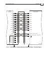
Table 3-5: Main Encoder Buffered Outputs or Emulated Encoder Outputs on FEEDBACK B -
Pin Assignments
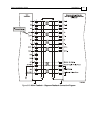
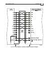
FEEDBACK B, on the front of the Tuba, has a 15-pin D-sub plug. Connect the Auxiliary
Feedback cable, from the controller or other device, to FEEDBACK B using a 15-pin D-Sub
socket with a metal housing. When assembling the Auxiliary Feedback cable, follow the
instructions in Section
3.4.4 (Feedback and Control Cable Assemblies).
Tuba Installation Guide Installation
MAN-TUBIG (Ver. 1.3)
3-25