


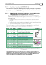
3.4.7.4 Pulse-and-Direction Input Option on FEEDBACK B
(YA[4]=0)
This mode is used for input of differential or single-ended pulse-and-direction position
commands on Port B1. In this mode Port B2 provides differential buffered pulse-and-
direction outputs for another axis.
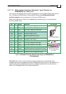
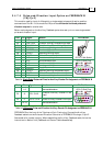
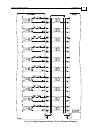
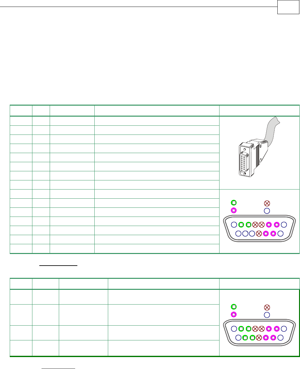
Below are the signals on the Auxiliary Feedback ports when set up to run as a single-ended
pulse-and-direction input:
Port Pin Signal Function Pin Position
- 1 N.C.
do not connect this pin
B1 2 DIR/CHB
Direction/Auxiliary Channel B high input
B1 3 PULS/CHA
Pulse/Auxiliary Channel A high input
PWR 4 +5V
Encoder supply voltage
PWR 5 SUPRET
Encoder supply return
B2 6 CHAO
Buffered Channel A output
B2 7 CHBO
Buffered Channel B output
- 8 N.C.
do not connect this pin
CO
R
0
1
6
A
15 Pin D-Sub Socket
- 9 N.C.
do not connect this pin
- 10 N.C.
do not connect this pin
- 11 N.C.
do not connect this pin
PWR 12 SUPRET
Supply Return
B2 13 CHAO-
Buffered Channel A complement output
B2 14 CHBO-
Buffered Channel B complement output
- 15 N.C.
do not connect this pin
15 Pin D-Sub Plug
8
15
1
9
Port B1
Port B2
Power
N.C.
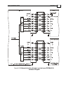
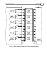
Table 3-8: Single-Ended Pulse-and-Direction Auxiliary Encoder Pin Assignment on FEEDBACK B
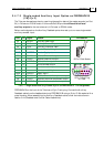
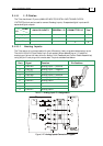
Port Pin Signal Function Pin Position
1~9
same as table above
B1 10 DIR-/CHB-
Direction/Auxiliary Channel B low
input
B1 11 PULS-/CHA-
Pulse/Auxiliary Channel A low input
12~15
same as table above
15 Pin D-Sub Plug
8
15
1
9
Port B1
Port B2
Power
N.C.
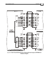
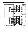
Table 3-9: Differential Pulse-and-Direction Auxiliary Encoder Pin Assignment on FEEDBACK B
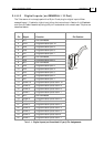
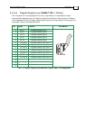
FEEDBACK B on the front of the Tuba has a 15-pin D-sub plug. Connect the Auxiliary
Feedback cable from the Pulse and Direction Controller to FEEDBACK B using a 15-pin D-
Sub socket with a metal housing. When assembling the Auxiliary Feedback cable, follow the
instructions in Section
3.4.4 (Feedback and Control Cable Assemblies).
Tuba Installation Guide Installation
MAN-TUBIG (Ver. 1.3)
3-31