


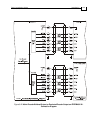
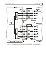
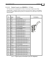
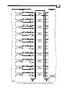

3.4.8.2 Digital Inputs (on GENERAL I/O Port)
The Tuba servo drive is equipped with a 25-pin D-sub plug for digital inputs. When
assembling an I/O cable for digital input follow the instructions in Section 3.4.4 (Feedback
and Control Cable Assemblies) using a 25-pin D-sub socket with a metal case. The pins are
described below.
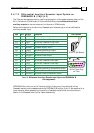
Pin Signal Function Pin Position
1 N.C. Not Connected
2 IN10 Programmable input 10
3 IN9 Programmable input 9
4 IN8 Programmable input 8
5 IN7 Programmable input 7
6 N.C. Not Connected
7 IN6 Programmable input 6
8 N.C. Not Connected
9
IN5 Programmable input 5
10
IN4 Programmable input 4
11 IN3 Programmable input 3
12 IN2 Programmable input 2
13 IN1 Programmable input 1
14 INRET10 Programmable inputs return 10
15 INRET9 Programmable inputs return 9
16 INRET8 Programmable inputs return 8
17 INRET7 Programmable inputs return 7
18 N.C. Not Connected
19 INRET6 Programmable inputs return 6
20 N.C. Not Connected
21 INRET5 Programmable inputs return 5
22 INRET4 Programmable inputs return 4
23 INRET3 Programmable inputs return 3
24 INRET2 Programmable inputs return2
25 INRET1 Programmable inputs return 1
Table 3-11: Digital Inputs (on Committed I/O port) Pin Assignments
Tuba Installation Guide Installation
MAN-TUBIG (Ver. 1.3)
3-34