


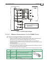
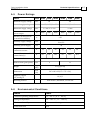
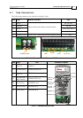
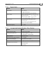
A.7 Tuba Connections
The following connectors are used for wiring the Tuba.
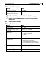
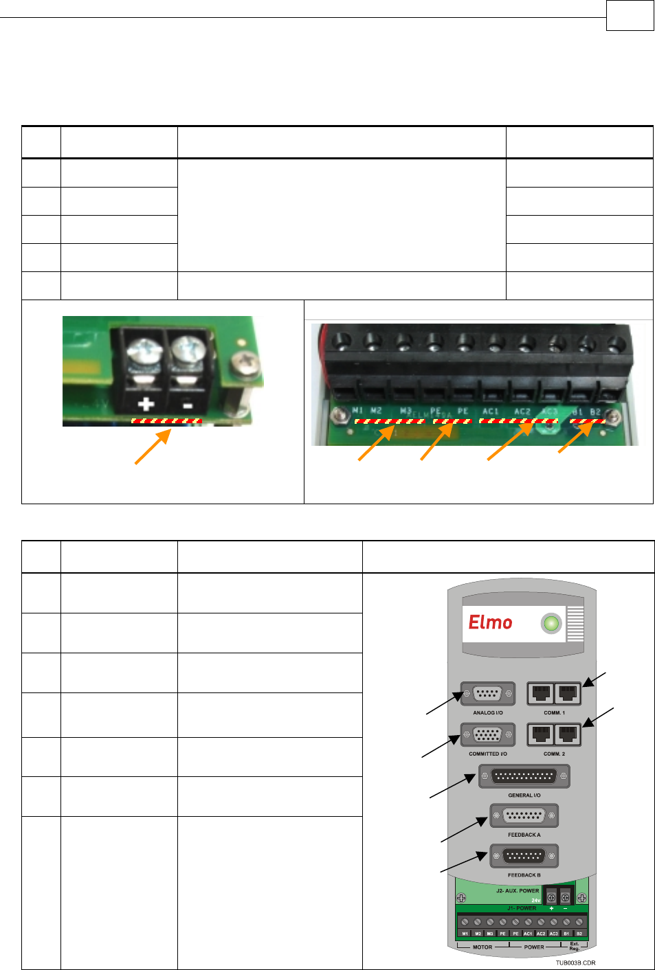
Pins
Type Maker & Part No. Port
5
Motor M1, M2, M3
2 Ground PE, PE
3 Power AC1, AC2, AC3
2 DC Link
10 pole 8 mm pitch Molex terminal block
B1, B2
2 Auxiliary Power 2 pole 0.325” (8 mm) pitch Molex terminal strip +, - (24V)
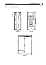
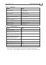
Connector Location
Table A-1: Connectors on the Bottom of the Tuba
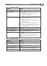
Pins Type Port Connector Location
8 RJ-45 x 2 COMM. 1
9 D-Sub Socket ANALOG INPUTS
8 RJ-45 x 2
COMM. 2
15
D-Sub Socket
High Density
COMMITTED I/O
25 D-Sub Plug GENERAL I/O
15 D-Sub Socket FEEDBACK A
15 D-Sub Plug FEEDBACK B
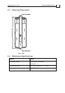
Table A-2: Connectors on the Tuba
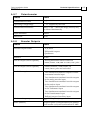
CANopen
FEEDBACK A
FEEDBACK B
RS-232
DIGITAL
INPUTS
ANALOG
INPUTS
DIGITAL
OUTPUTS
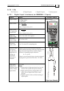
Ground
Motor
Power Ext. DC Link
Auxiliary Powe
r
Tuba Installation Guide Technical Specifications
MAN-TUBIG (Ver. 1.3)
A-6