


3.4.7.4 Pulse-and-Direction Input Option on FEEDBACK B (YA[4]=0) .......... 3-31
3.4.8
I/O Cables.............................................................................................................. 3-33
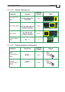
3.4.8.1 Analog Inputs............................................................................................ 3-33
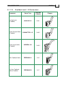
3.4.8.2 Digital Inputs (on GENERAL I/O Port)................................................. 3-34
3.4.8.3 Digital Outputs (on COMMITTED I/O Port) ........................................3-36
3.4.9
Communication Cables........................................................................................ 3-38
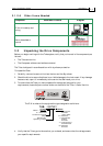
3.4.9.1 RS-232 Communication (on the COMM.1 Port)..................................... 3-38
3.4.9.2 CANopen Communication (on the COMM.2 Ports) ............................. 3-39
3.5 Powering Up............................................................................................................3-41
3.6 Initializing the System ............................................................................................3-41
Appendix: Technical Specifications ....................................................................................A-1
A.1 Features.....................................................................................................................A-1
A.1.1 Motion Control Modes.......................................................................................... A-1
A.1.2 Advanced Positioning Motion Control Modes.................................................. A-1
A.1.3 Advanced Filters and Gain Scheduling .............................................................. A-1
A.1.4 Fully Programmable .............................................................................................. A-1
A.1.5 Feedback Options................................................................................................... A-1
A.1.6 Input/Output ......................................................................................................... A-2
A.1.7 Built-In Protection.................................................................................................. A-2
A.2 Tuba Dimensions .....................................................................................................A-3
A.3 Mounting Dimensions.............................................................................................A-4
A.4 Mechanical Specifications .......................................................................................A-4
A.5 Power Ratings...........................................................................................................A-5
A.6 Environmental Conditions......................................................................................A-5
A.7 Tuba Connections.....................................................................................................A-6
A.7.1 Auxiliary Supply.................................................................................................... A-7
A.8 Control Specifications..............................................................................................A-7
A.8.1 Current Loop .......................................................................................................... A-7
A.8.2 Velocity Loop.......................................................................................................... A-8
A.8.3 Position Loop.......................................................................................................... A-8
A.9 Feedbacks..................................................................................................................A-9
A.9.1 Feedback Supply Voltage ..................................................................................... A-9
A.9.2 Incremental Encoder Input................................................................................... A-9
A.9.3 Digital Halls.......................................................................................................... A-10
A.9.4 Interpolated Analog Encoder (Sine/Cosine) ................................................... A-10
A.9.5 Resolver................................................................................................................. A-11
A.9.6 Tachometer*.......................................................................................................... A-11
A.9.7 Potentiometer ....................................................................................................... A-12
A.9.8 Encoder Outputs .................................................................................................. A-12
A.10 I/Os A-13
A.10.1 Digital Input Interfaces (on GENERAL I/O port)........................................... A-13
A.10.2 Digital Output Interface (on COMMITTED I/O port) ................................... A-14
A.10.3 Analog Input......................................................................................................... A-15
A.11 Communications ....................................................................................................A-15
A.12 Pulse Width Modulation (PWM)..........................................................................A-16
A.13 Single-phase Operation .........................................................................................A-16
A.14 Standards Compliance...........................................................................................A-17
A.14.1 Quality Assurance................................................................................................ A-17
A.14.2 Design.................................................................................................................... A-17
A.14.3 Safety ..................................................................................................................... A-17
A.14.4 EMC ....................................................................................................................... A-17
A.14.5 Workmanship....................................................................................................... A-17
A.14.6 PCB......................................................................................................................... A-18
Tuba Installation Guide Contents
MAN-TUBIG (Ver. 1.3)
ii