


Contents
Chapter 1: Safety Information ...............................................................................................1-1
1.1 Warnings....................................................................................................................1-2
1.2 Cautions .....................................................................................................................1-2
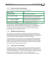
1.3 Directives and Standards .........................................................................................1-3
1.4 CE Mark Conformance.............................................................................................1-3
1.5 Warranty Information...............................................................................................1-3
Chapter 2: Introduction...........................................................................................................2-1
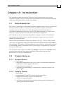
2.1 Drive Description......................................................................................................2-1
2.2 Product Features .......................................................................................................2-1
2.2.1 Current Control....................................................................................................... 2-1
2.2.2 Velocity Control ...................................................................................................... 2-1
2.2.3 Position Control ...................................................................................................... 2-2
2.2.4 Advanced Position Control (Advanced model only) ............................................. 2-2
2.2.5 Communication Options........................................................................................ 2-2
2.2.6 Feedback Options.................................................................................................... 2-2
2.2.7 Fault Protection ....................................................................................................... 2-3
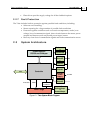
2.3 System Architecture..................................................................................................2-3
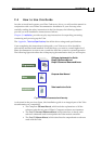
2.4 How to Use this Guide .............................................................................................2-4
Chapter 3: Installation ............................................................................................................3-1
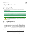
3.1 Before You Begin.......................................................................................................3-1
3.1.1 Site Requirements ................................................................................................... 3-1
3.1.2 Hardware Requirements........................................................................................ 3-1
3.1.2.1 AC Input Requirements .............................................................................3-1
3.1.2.2 Recommended Wire Cross-sections (All Models) ................................... 3-1
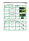
3.1.2.3 Power Connectors....................................................................................... 3-2
3.1.2.4 Communication Connectors ......................................................................3-2
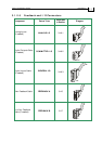
3.1.2.5 Feedback and I/O Connectors................................................................... 3-3
3.1.2.6 Other Items Needed.................................................................................... 3-4
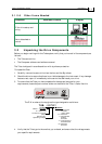
3.2 Unpacking the Drive Components..........................................................................3-4
3.3 Mounting the Tuba ...................................................................................................3-5
3.3.1 Mounting Directly onto Wall ................................................................................ 3-5
3.3.2 Mounting on a DIN Rail......................................................................................... 3-6
3.4 Connecting the Cables ..............................................................................................3-7
3.4.1 Wiring the Tuba ...................................................................................................... 3-7
3.4.2 Connecting the Power Cables ............................................................................. 3-10
3.4.2.1 Connecting the Motor Cable.................................................................... 3-11
3.4.2.2 Connecting the Main Power Cable.......................................................... 3-12
3.4.2.3 Connecting the DC Link Cable ................................................................3-12
3.4.3
Connecting the Auxiliary Supply Cable (24v) .................................................. 3-13
3.4.4 Feedback and Control Cable Assemblies .......................................................... 3-14
3.4.5 Main Feedback Cable (Feedback A)................................................................... 3-15
3.4.6 Main and Auxiliary Feedback Combinations ................................................... 3-23
3.4.7 Auxiliary Feedback (FEEDBACK B) .................................................................. 3-25
3.4.7.1 Main Encoder Buffered Outputs or Emulated Encoder Outputs Option
on FEEDBACK B (YA[4]=4)..................................................................................... 3-25
3.4.7.2 Differential Auxiliary Encoder Input Option on FEEDBACK B (YA[4]=2)
........................................................................................................ 3-27
3.4.7.3 Single-ended Auxiliary Input Option on FEEDBACK B (YA[4]=2)..... 3-29
Tuba Installation Guide
MAN-TUBIG (Ver. 1.3)
i