


A.10 I/Os
The Tuba has: 10 Digital Inputs 6 Digital Outputs 2 Analog Inputs
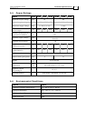
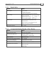
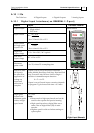
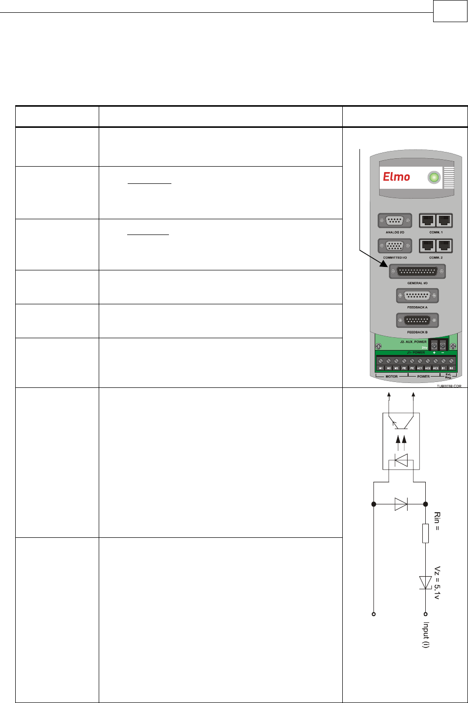
A.10.1 Digital Input Interfaces (on GENERAL I/O port)
Feature Details Connector Location
Type of input
Optically isolated
Single ended
PLC level
Input current
Ω
−
=
2500
5.6 VVin
Iin
* Iin = 2.2 mA @ Vin = 12 V
Input current
for high speed
inputs 5 & 6
Ω
−
=
1250
5.6 VVin
Iin
* Iin = 4.4 mA @ Vin = 12 V
High-level
input voltage
12 V < Vin < 30 V, 24 V typical
Low-level
input voltage
0 V < Vin < 6.5 V
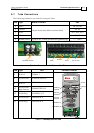
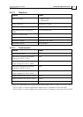
Minimum
pulse width
> 4 x TS, where TS is sampling time
Execution time
(all inputs):
the time from
application of
voltage on
input until
execution is
complete
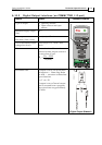
If input is set to one of the built-in functions —
Home, Inhibit, Hard Stop, Soft Stop, Hard and Soft
Stop, Forward Limit, Reverse Limit or Begin —
execution is immediate upon detection:
0 < T < 4 x TS
If input is set to General input, execution depends
on program. Typical execution time: ≅ 0.5 msec.
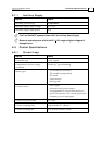
High-speed
inputs 5 & 6 -
minimum pulse
width, in high-
speed mode
T < 5 µsec
Notes:
Home mode is high-speed mode and can be
used for fast capture and precise homing.
High speed input has a digital filter set to
same value as digital filter (EF) of main
encoder.
Highest speed is achieved when turning on
optocouplers.
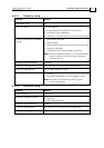
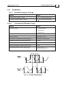
2.5K
I
n
p
u
t
R
e
t
u
r
n
(
i
)
DIGINPUT
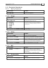
Digital Input Schematic
DIGITAL INPUTS
Tuba Installation Guide Technical Specifications
MAN-TUBIG (Ver. 1.3)
A-13