


Digital Outputs · 3-8
Digital Outputs · 3-36
Dimensions · A-3
DIN rail mounting · 3-6
Documentation Hierarchy · 2-4
E
Environmental conditions · A-5
External Resistor (BR1) Regeneration
Option · 3-12
F
Fault protection · 2-3
Feedback
Connector · 3-14
Options · 2-2, A-8
Supply voltage · A-9
Feedback A · 3-15
FEEDBACK A · 3-8
FEEDBACK A port · 3-3
Feedback and Control Cable Assemblies ·
3-14
Feedback B
Single-ended Auxiliary Input Option · 3-29
Feedback B · 3-25
Differential Auxiliary Encoder Input
Option · 3-27
Emulated Encoder Outputs · 3-25
Main Encoder Buffered Outputs · 3-25
Pulse-and-Direction Input Option · 3-31
FEEDBACK B · 3-8
FEEDBACK B port · 3-3
Feedback options · A-9, A-10, A-12, A-13
Feedback Options · A-1
G
GENERAL I/O · 3-8
GENERAL I/O port · 3-3
GENERAL I/O Port · 3-34
Grounding · 1-1
Auxiliary power cable · 3-13
CANopen cables · 3-39
Main feedback cables · 3-14
Motor cables · 3-11
RS-232 cable · 3-38
H
Hardware requirements · 3-1
I
I/O cables · 3-33
I/O Cables
Analog inputs cable · 3-33
Incremental Encoder · 3-15, 3-17
Initializing the Tuba · 3-41
Input/Output · A-2
Installation · 3-1
Interpolated Analog Encoder · 3-15, 3-18
M
Main Feedback · 3-8
Main feedback cable · 3-15
Main Feedback Cable · 3-15
Main Feedback Cable Pin Assignments · 3-
15, 3-16
Main power cable · 3-12
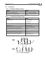
Main Power Supply Connection Diagram ·
3-12
Mains, Motor Power & External Regeneration
·
3-8
Maximum
Relative humidity · 3-1
Mechanical Specifications · A-4
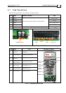
Mini-Saxophone
Connectors · 3-8
Motion Control Modes · A-1
Motor cables · 3-11
Mounting Dimensions · A-4
Mounting the Tuba · 3-5
Directly on wall · 3-5
On DIN rail · 3-6
P
Ports
ANALOG I/O · 3-8
COMM. 1 · 3-8
COMM. 2 · 3-8
Tuba Installation Guide Index
MAN-TUBIG (Ver. 1.3)
I-2