


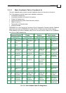
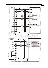
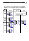
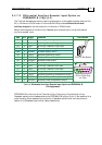
3.4.6 Main and Auxiliary Feedback Combinations
The Main Feedback is always used in motion control devices whereas Auxiliary Feedback is
often, but not always used. The Auxiliary Feedback connector on the Tuba, “FEEDBACK B”
has two ports, Port B1 and Port B2. When used in combination with the Main Feedback port,
“FEEDBACK A”, the ports can be set, by software, as follows:
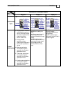
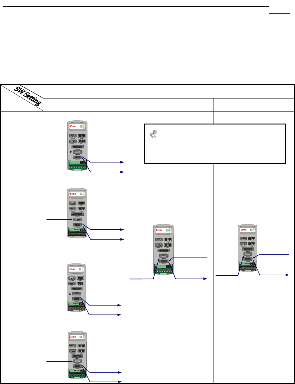
FEEDBACK B Ports B1 and B2
FEED-
BACK A
YA[4] = 4 YA[4] = 2 YA[4] = 0
Incremental
Encoder
Input
B1 - output
B2 - output
same as B1
A - input
Analog
Encoder
Differential
and
Buffered
Main
Encoder
Signal
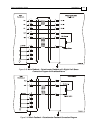
Interpolated
Analog
(Sin/Cos)
Encoder
Input
B1 - output
B2 - output
same as B1
A - input
Analog
Encoder
Analog Encoder
Position Data
Emulated in
Incremental
Encoder Format
(signals are
quadrature,
differential &
buffered)
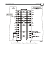
Resolver
Input
B1 - output
B2 - output
same as B1
A - input
Resolver
Resolver
Position
Data Emulated
in Incremental
Encoder Format
(signals are
quadrature,
differential &
buffered)
Tachometer
Input
B1 - output
B2 - output
same as B1
A - input
Tachometer
Tachometer
Position
Data Emulated
in Incremental
Encoder Format
(signals are
quadrature,
differential &
buffered)
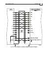
B1 - input
B2 - output
Differential
or
Single-ended
Auxiliary
Incremental
Encoder
Differential
and Buffered
output of B1
A - input
Incremental
Encoder
or
Analog
Encoder
or
Resolver
or
Tachometer
or
Potentiometer
B1 - input
B2 - output
Differential or
Single-ended
Pulse &
Direction
Commands
Differential
and Buffered
output of B1
A - input
Incremental
Encoder
or
Analog
Encoder
or
Resolver
or
Tachometer
or
Potentiometer
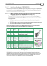
Feedback Ports B1 and B2 are not to be
confused with the DC Link connectors
on the 10-pin terminal block.
Tuba Installation Guide Installation
MAN-TUBIG (Ver. 1.3)
3-23