


Operator Control Panel and Display
92
8.0 OPERATOR CONTROL PANEL AND DISPLAY
8.1 Introduction
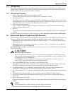
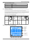
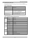
The operator control panel and display is located on the front door of the UPS. The panel is the access
point for operator control and monitoring of all measured parameters, UPS and battery status and of
event and alarm logs.
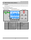
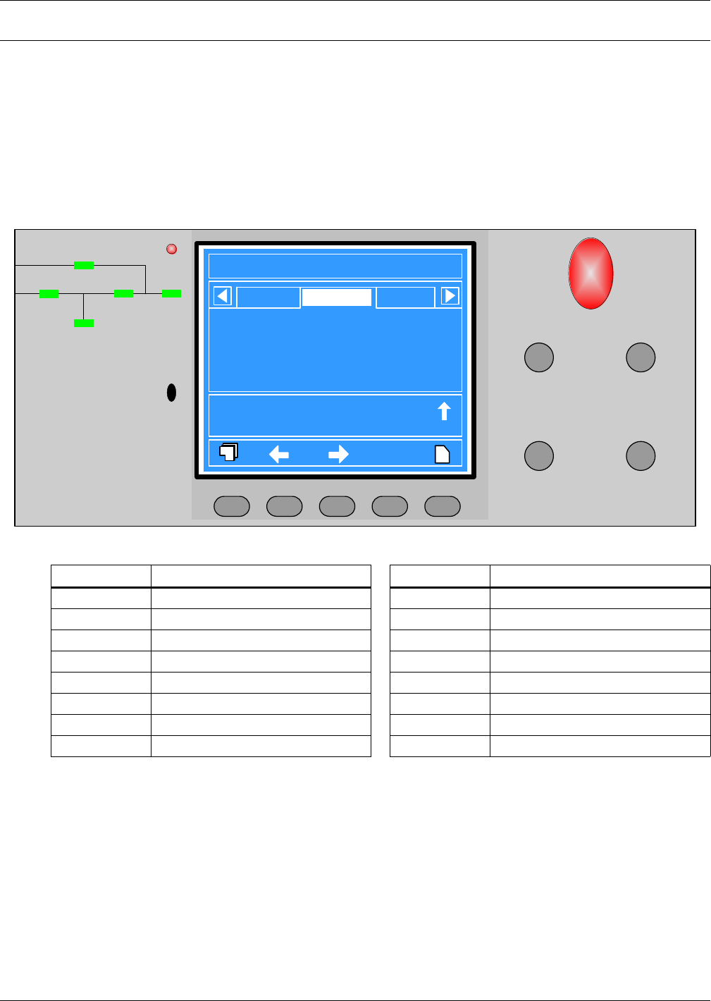
Figure 67 UPS control and display panel
Table 12 UPS control and display panel components
Component #
Function
Button
Function
1 Rectifier (Input AC to DC) EPO Emergency Power Off button
2 Battery (DC Back-up) Inverter ON Inverter start button
3 Bypass Input Inverter OFF Inverter shutdown button
4 Inverter (DC to AC) Fault Clear Reset button
5 Load (AC Output) Silence On/Off Audible Alarm Mute
6 UPS Status and Alarm indicator — —
7 Audible Alarm (Buzzer)_ F1-F4, Help LCD Menu keys
8 Emergency Power Off Button cover — —
EPO
INVERTER ON
FAULT CLEAR SILENCE ON/OFF
3
1
2
45
Status
?
Rotary SW. normal pos.
17:2407-07
Manual turn on
Normal mode
17:29
17:30
07-07
07-07
7
8
6
INVERTER OFF
F2 F3 F4 HELPF1
LoadBypass Output
Liebert NX
200kVA 3X3
2005-10-22
Single
17:32:20
Normal
L1-N/L2
229.5
24.5
49.97
397.5
0.99
L2-N/L3
229.5
24.5
49.97
397.5
1.00
L3-N/L1
229.5
24.5
49.97
397.5
0.99
L1-N/L2 voltage (V)
L-N current (A)
Frequency (Hz)
L-L voltage (V)
Power Factor
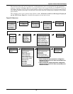
The operator control panel is divided into three functional areas
Mimic Power Flow Chart Graphic LCD monitor with menu keys Direct Access keys